


Special offers from our partners!

Find Replacement BBQ Parts for 20,308 Models. Repair your BBQ today.

Barbecue Grills
LTR50001038, Rev. C
Built-in Construction
www.calamebbq.com
4
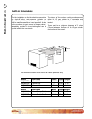
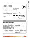
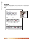
Built-in Dimensions
Model Description Width Depth Height
BBQ08873P 3 Burner Grill 23 3/8” 22¼” 9 ¼”
BBQ08874CP 4 Burner Grill 31” 22¼” 9 ¼”
BBQ08875CP 5 Burner Grill 38 ½” 22¼” 9 ¼”
W
ID
T
H
W
ID
T
H
W
ID
T
H
W
ID
T
H
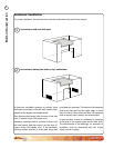
Minimum
Clearance
12” Minimum Distance
Between Grill and Side Burner
Minimum
Clearance
Screen Vents
W
ID
T
H
W
ID
T
H
WIDTH
DEPTH
WIDTH
WIDTH
DEPTH
WIDTH
WIDTH
WIDTH
DEPTH
DEPTH
DEPTH
HEIGHT
HEIGHT
HEIGHT
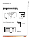
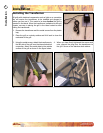
Burner
Locking Pin
Burner
Locking Pin
Model Description Width Depth Height
BBQ08954P Deluxe Side by Side Burner 25 ¼” 12 ½” 7 ¼”
BBQ08899P Deluxe Double Side Burner 12 ¼” 22” 7 ¼”
The dimensions shown below are for Cal Flame appliances only.
Plan the installation so that the electrical connection,
gas shut-off valve, and pressure regulator are
accessible inside the base enclosure. The gas valve
shall be readily accessible for hand operation. A door
on the enclosure to gain access to the gas valve is
acceptable, provided it is non-locking and can be
opened without the use of tools.
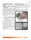
The design of the outdoor cooking enclosure must
allow the LP gas cylinder to be connected and
disconnected and the connections inspected and
tested.
There must be a minimum clearance of 2 inches
(51mm) between the oor of the LP-gas cylinder
enclosure and the ground.