


Special offers from our partners!

Find Replacement BBQ Parts for 20,308 Models. Repair your BBQ today.
Buy Weber Grill Parts. It couldn't be easier. Find your Weber parts here.
20
WWW.WEBER.COM
®
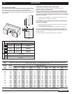
Table
10-1
Maximum Capacity of Pipe in Cubic Feet of Gas per Hour for Gas Pressures of 0.5 psi or Less and a Pressure Drop of 0.3 Inch
Water Column. (Based on a 0.60 Specifi c Gravity Gas)
Nominal
Iron Pipe
Size
(Inches)
Internal
Diameter
(Inches)
Length of Pipe (Feet)
10 20 30 40 50 60 70 80 90 100 125 150 175 200
1/4 .364 32 22 18 15 14 12 11 11 10 98876
3/8 .493 72 49 40 34 30 27 25 23 22 21 18 17 15 14
1/2 .622 132 92 73 63 56 50 46 43 40 38 34 31 28 26
3/4 .824 278 190 152 130 115 105 96 90 84 79 72 64 59 55
1 1.049 520 350 285 245 215 195 180 170 160 150 130 120 110 100
1 1/4 1.380 1050 730 590 500 440 400 370 350 320 305 275 250 225 210
1/12 1.160 1600 1100 890 760 670 610 560 530 490 460 410 380 350 320
2 2.067 3050 2100 1650 1450 1270 1150 1050 990 930 870 780 710 650 610
2 1/2 2.469 4800 3300 2700 2300 2000 1850 1700 1600 1500 1400 1250 1130 1050 980
3 3.068 8500 5900 4700 4100 3600 3250 3000 2800 2600 2500 2200 2000 1850 1700
4 4.026 17500 12000 9700 8300 7400 6800 6200 5800 5400 5100 4500 4100 3800 3500
© 1997 National Fire Protection Association, Inc. and International Approval Services - U.S., Inc. All Rights Reserved.
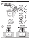
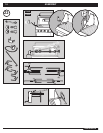
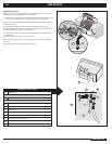
TYPICAL BULK PROPANE GAS SUPPLY INSTALLATION
We recommend that this installation be done by a LICENSED professional.
GENERAL SPECIFICATIONS FOR PIPING
Note - Contact your local municipality for building codes regulating outdoor gas grill
installations. In absence of Local Codes, you must conform to the latest edition of the
National Fuel Gas Code ANSI Z223.1/NFPA 54, Natural Gas and Propane Installation
Code, CSA B149.1, or Propane Storage and Handling Code, B149.2, or the Standard for
Recreational Vehicles, ANSI A 119.2/NFPA 1192, and CSA Z240 RV Series, Recreational
Vehicle Code, as applicable.
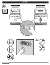
• This grill is designed to operate at 11 inches of water column pressure. An LP in
line regulator may be necessary for this pressure.
ƽ CAUTION: If young children are in the area, a locking valve
should be considered.
• Pipe compound should be used which is resistant to the action of liquid propane
gas when gas connections are made.
• The gas connections must be fi rmly attached to rigid, permanent construction.
Note: The information provided in this manual is general for typical installations. We
cannot cover all possible installation ideas. We recommend, prior to installation, that
you contact your municipality for local building codes and your local fi re department for
installation verifi cation.
If you have any questions, contact Customer Service at 1-800-446-1071.
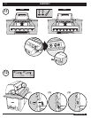
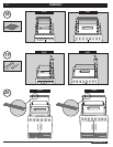
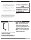
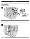
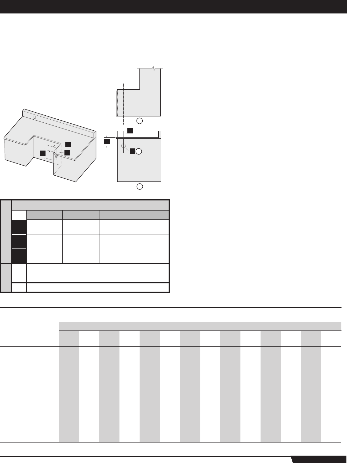
BUILT-IN GAS LINE LOCATIONS
Note: Leave an access in the “island” structure for gas supply and regulator service that
is not inside the grill structure. Weber
®
has a gas line and regulator access door (part #
36311) available from your dealer or call Customer Service at 1-800-446-1071.
Note: Area should be kept clear of sharp, jagged, or extremely abrasive surfaces to avoid
possible damage to gas supply lines. Exercise caution when pulling gas lines through
built-in structure.
1
1
2
2
3
3
a
b
c
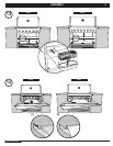
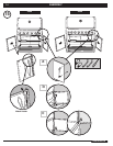
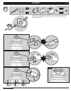
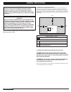
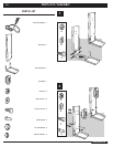
DIMENSIONS
BUILT-IN GAS LINE LOCATIONS
SILVER GOLD TOLERANCES
1
3 3/4˝
(95.3 mm)
3 3/4˝
(95.3 mm)
+1/8˝(
3.8
mm)
- 1/8˝(
3.8
mm)
2
6 1/4˝
(158.8 mm)
6 1/4˝
(158.8 mm)
+1/8˝(
3.8
mm)
- 1/8˝(
3.8
mm)
3
2 1/2˝
(63.5 mm)
2 1/2˝
(63.5 mm)
+1/8˝(
3.8
mm)
- 1/8˝(
3.8
mm)
a
Plan View Left
b
Side View
c
Gas Inlet
GAS SUPPLY