


Special offers from our partners!

Find Replacement BBQ Parts for 20,308 Models. Repair your BBQ today.
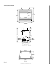
NOTE: DIAGRAMS & ILLUSTRATION NOT TO SCALE.
9
To light the burner; rotate the gas valve control
knob counterclockwise to the “ON” position.
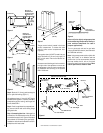
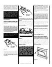
Step 14. Installing the Hood Assembly –
Attach the hood assembly over the firebox
opening with three (3) screws.
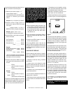
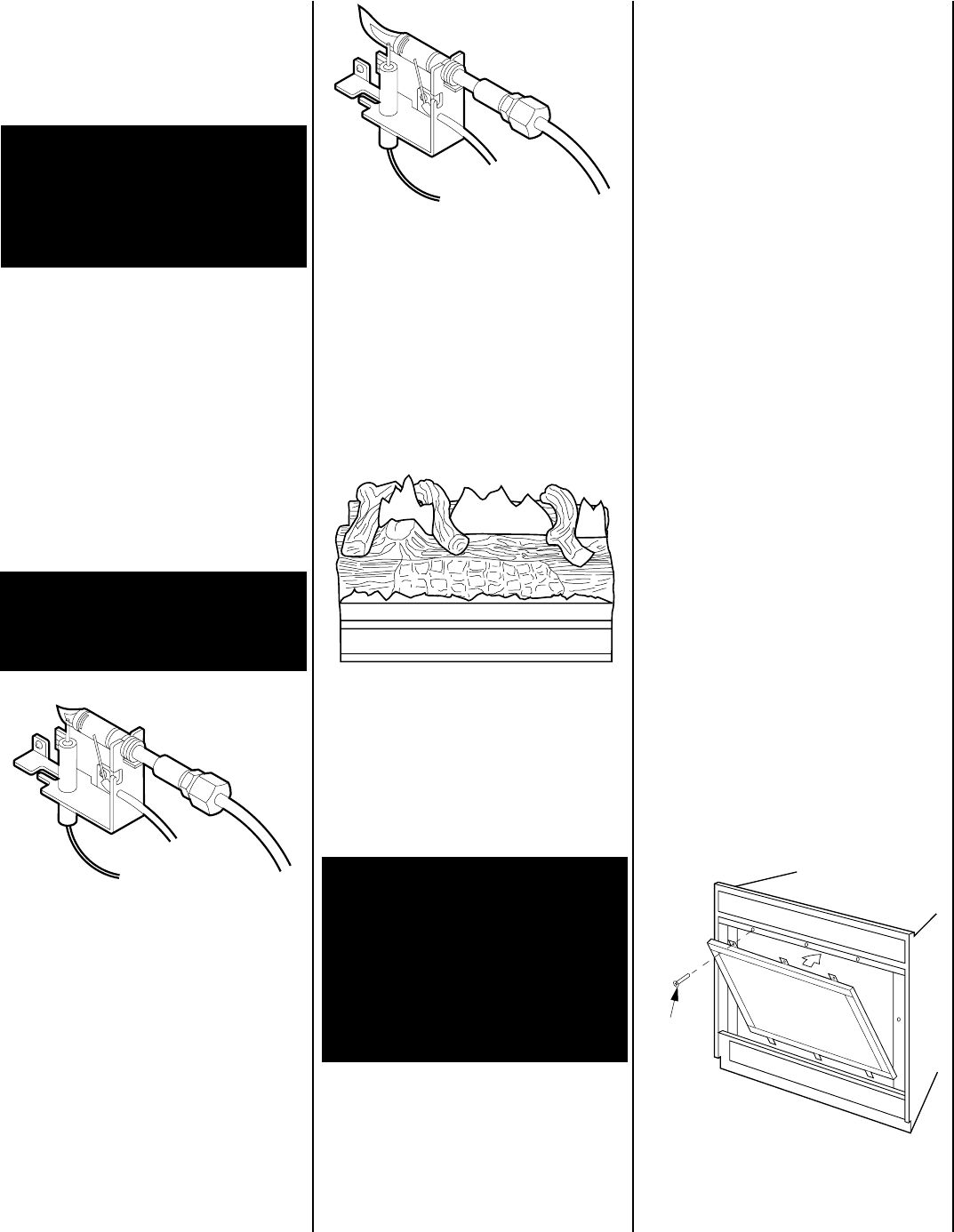
Step 15. Installing the Screen Assembly –
Position the screen assembly in front of the
firebox opening, with the joint in the gasket
down (
Figure 18
). Locate the three (3) tabs at
the bottom edge of the frame into the three (3)
brackets at the base of the fireplace front
opening. Lean the frame back towards the
fireplace. Install the three (3) 1/4"-20 x 1"
Phillips pan head screws removed previously
and tighten to secure.
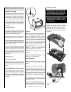
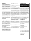
In normal operation, at full rate, after 15 min-
utes the following flame appearance should be
observed:
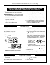
Rear Burner Flame Characteristics – The rear
flames should be yellow. The flames should
extend about 3 – 4" above the front log for
natural gas and 2 – 3" above for propane
(L.P.G.) gas (
Figure 17
).
When first lighting the appliance, it will take a
few minutes for the line to purge itself of air.
Once purging is complete, the pilot and burner
will light and operate as indicated in the instruc-
tion manual. Subsequent lightings of the appli-
ance will not require such purging. Inspect the
pilot flame (remove logs, if necessary, handling
carefully).
The pilot flame should be steady, not lifting or
floating. Flame should be blue in color with
traces of orange at the outer edge.
The top 3/8" (10 mm) at the pilot thermocouple
should be engulfed in the pilot flame (NG only).
Replace logs if removed for pilot inspection.
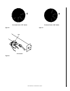
Screws
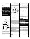
Step 13. Checking the System – With gas line
installed run initial system checkout before
closing up the front of the unit. Follow the pilot
lighting instructions on pages 14 and 16.
Note: Instructions are also found on the pull
out panel located on the bottom surface of the
appliance.
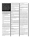
Figure 16
Figure 18
Standard (Manual)
Version Shown
After setting the logs into position as described
above, ensure they are properly and firmly
situated. The heater will not function as in-
tended if the logs are not correctly positioned.
Periodically check the positioning of the logs.
WARNING: FAILURE TO POSITION THE
PARTS IN ACCORDANCE WITH THESE
DIAGRAMS OR FAILURE TO USE ONLY
PARTS SPECIFICALLY APPROVED WITH
THIS HEATER MAY RESULT IN PROP-
ERTY DAMAGE OR PERSONAL INJURY.
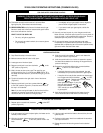
Flame Appearance
REFER TO THE OPERATING INSTRUCTIONS
LOCATED AT THE BACK OF THIS MANUAL
BEFORE LIGHTING THE HEATER TO OBSERVE
THE FLAMES.
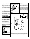
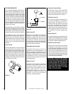
Flames from the pilot, front and rear burner
should be visually checked as soon as the
heater is installed. In addition a periodic visual
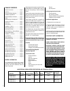
check of the flames should be made. The pilot
flame should always be present when the heater
is in operation and should just envelope the tip
of the thermocouple (
Figure 15
).
WARNING: NO ADJUSTMENTS ARE TO
BE MADE TO THE ODS PILOT SYSTEM.
TAMPERING WITH THIS SYSTEM CAN
BE EXTREMELY HAZARDOUS.
Figure 15
An incorrect pilot flame is shown in
Figure 16
.
This pilot flame will cause the thermocouple to
cool. When the thermocouple cools, the heater
will shut off. If pilot flame pattern is incorrect,
or if heater shuts off, contact your service
representative.
Figure 17
Main Burner – The flames at the front burner
holes will be blue becoming yellowish as they
hit the bark-like texture of the base and front
face of the front log (
Figure 17
).
Appliance Operation
WARNING: THE LOWER CONTROL COM-
PARTMENT AREA AND LOWER CONTROL
COMPARTMENT ACCESS DOOR ARE EX-
TREMELY HOT WHEN THE APPLIANCE IS
IN OPERATION. EXERCISE EXTREME CARE
WHEN ACCESSING THIS AREA. TOUCH
ONLY THE FAR ENDS OF THE LOWER
CONTROL COMPARTMENT DOOR WHEN
OPENING WHILE THE APPLIANCE IS HOT.
Standard (Manual)
Version Shown