


Special offers from our partners!

Find Replacement BBQ Parts for 20,308 Models. Repair your BBQ today.
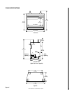
NOTE: DIAGRAMS & ILLUSTRATION NOT TO SCALE.
6
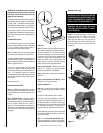
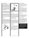
The gas control valve is located in the lower
control compartment. To access the valve
open the lower control compartment door
(
Figure 9
).
The regulator has a 3/8" NPT thread inlet port
and is fitted with a 3" (76 mm) long nipple, ³⁄₈"
NPT on both ends. Plan the connections ac-
cordingly.
We recommend that the gas line be routed for
the right side of the appliance to ensure ad-
equate access to the rear lower compartment
for installation and servicing of the optional
FAB-1100 blower.
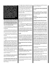
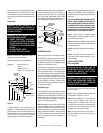
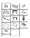
Figure 6
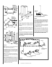
Figure 8
37-1/4"
(946 mm)
37"
(940 mm)
15-1/2"
(394 mm)
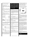
Figure 9
Secure all joints tightly using appropriate
tools and sealing compounds (ensure pro-
pane resistant compounds are used in
propane applications).
Turn on gas supply and test for gas leaks,
using a gas leak test solution (also referred to
as bubble leak solution).
Note: Using a soapy water solution (50% dish
soap, 50% water) is an effective leak test
solution but it is not recommended, because
the soap residue that is left on the pipes/
fittings can result in corrosion over time. Never
use an open flame to check for leaks.
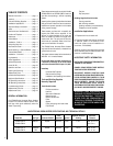
Figure 4
37" (940mm)
15-1/2"
(394mm)
Outside Wall
Back Wall of
Chase/Enclosure
Including Finishing
Materials If Any.
Figure 5
37" (940mm)
58-1/2" (1486mm)
13-1/2"
(343mm)
29"
(737mm)
41"
(1041mm)
Back Wall of
Chase/Enclosure
Including Finishing
Materials If Any.
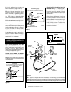
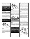
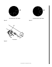
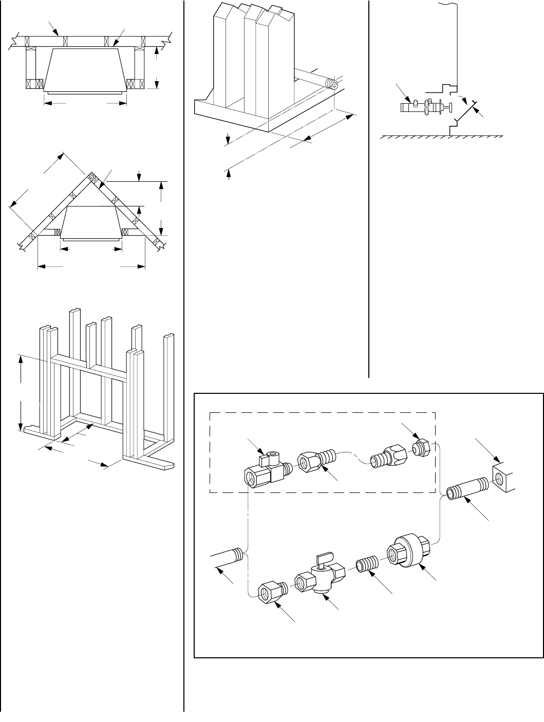
Step 2. Route a 1/2" (13 mm) gas line along the
left or right side framing (
Figure 7
).
All appliances have a 3" long 3/8" NPT nipple
installed at the regulator. To quickly and easily
complete the gas line routing, use the gas flex
line kit, Model GFLV.
Step 3. Position appliance into prepared fram-
ing, secure with 6d nails at the nailing flange
along each side.
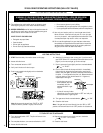
Step 4. Connecting Gas Line – Make gas line
connections. All codes require a shut-off valve
mounted in the supply line.
Figure 8
illustrates
two methods for connecting the gas supply.
Installation methods and materials must be in
compliance with local codes.
3"
(76 mm)
7"
(178 mm)
Figure 7
Gas Stub
1/2" x 3/8" Flare
Shut-Off Valve
3/8" Flex Tubing
3/8" NPT x 3/8"
Flare Fitting
3/8" Nipple, Standard
with all Units
3/8" Union
3/8" Close Nipple
3/8" Shut-Off Valve
1/2" x 3/8" Reducer
Gas Valve
Gas Flex Line Kit, Model GFLV
Control Valve
(Standard)
Lower Control
Compartment Door