


Special offers from our partners!

Find Replacement BBQ Parts for 20,308 Models. Repair your BBQ today.
7
Regency IG34 Gas Inbuilt Fireplace
INSTALLATION
GAS PIPE PRESSURE
TESTING
The appliance must be isolated from the gas
supply piping system by closing its individual
manual shut-off valve during any pressure
testing of the gas supply piping system at
test pressures equal to or less than 1/2 psig.
(3.45 kPa). Disconnect piping from valve at
pressures over 3.45 kPa (14" w.c.).
The manifold pressure is controlled by a
regulator built into the gas control, and should
be checked at the pressure test point.
Note: To properly check gas pressure,
both inlet and manifold pressures
should be checked using the valve
pressure ports on the valve.
1) Make sure the valve is in the "OFF"
position.
2) Loosen the "IN" (# 3) and/or "OUT" (# 4)
pressure tap(s), turning counterclockwise
with a 1/8" wide fl at screwdriver.
3) Attach manometer to "IN" and/or "OUT"
pressure tap(s) using a 5/16" (8mm) ID
hose.
4) Seal and or check the pilot outlet (# 8)
5) The pressure check should be carried out
with the unit burning and the setting should
be within the limits specifi ed on the safety
label.
6) When fi nished reading manometer, turn
off the gas valve, disconnect the hose and
tighten the screw (clockwise) with a 1/8"
fl at screwdriver. Screw should be snug,
but do not over tighten.
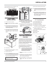
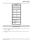
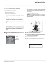
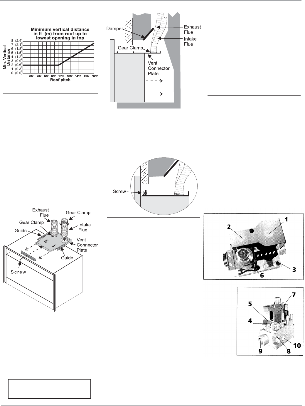
S.I.T. Valve Description
1) On-Off Solenoid Valve EV1
2) On-Off Solenoid Valve EV2
3) Inlet Pressure Test Point
4) Outlet Pressure Test Point
5) Connection for Pressure Regulator/
Combustion Chamber Compensation
6) Pressure Regulator for Minimum and
Maximum Outlet Pressure
7) Gas Outlet Pressure Electric Modulator
8) Pilot Outlet
9) Main Gas Outlet
10) Side Outlet
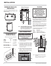
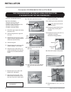
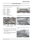
FLUE LINER
INSTALLATION
1) Cut the fl ex liner as required.
2) Mark the end of one liner to indicate
Inlet.
3) Connect the other end of the above liner to
the inlet side of the termination adaptor, seal
connection with high temperature silicone.
Secure with gear clamp.
4) Connect the 2nd liner to the exhaust side
of the adaptor, seal connection with high
temperature silicone. Secure with gear
clamp.
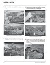
5) Install fl ashing.
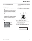
6) Insert both liners into chimney, passing
through the damper opening.
7) Install termination cap.
8) Connect the marked end of the liner to the inlet
collar of the vent connector plate marked with
an "I", seal connection with high temperature
silicone. Secure with gear clamp.
The Air Intake pipe must be attached to the
inlet air collar of the termination cap.
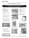
9) Connect the 2nd liner to the exhaust collar
marked with an "E", seal connection with
high temperature silicone. Secure with gear
clamp.
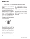
Be careful not to damage thermal insula-
tion when sliding on vent connector plate.
This could cause blockage.
Install to AS5601 (Australia) /
NZS 5262 (New Zealand)