


Special offers from our partners!

Find Replacement BBQ Parts for 20,308 Models. Repair your BBQ today.
6
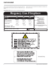
Regency IG34 Gas Inbuilt Fireplace
INSTALLATION
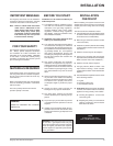
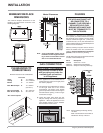
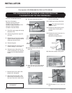
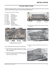
Mantel Clearances
Note: A non-combustible mantel may be
installed at a lower height if the fram-
ing is made of metal studs covered
with a non-combustible board.
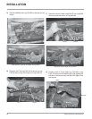
CLEARANCES TO
COMBUSTIBLES
Minimum Clearances to Combustibles
From Unit
Sides A 10" / 255mm
Ceiling B 47.5" / 1205mm
Mantel C 13" / 330mm
Max. Mantle Depth E 12" / 305mm
(see Dia. 2)
Min. Alcove Width F 48" / 1220 mm
Max. Alcove Depth G 36" / 915 mm
*No hearth required.
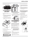
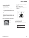
GAS CONNECTION
GAS CONNECTION WARNING:
Only persons licensed to work
with gas piping may make the
necessary gas connections
to this appliance.
1) If the appliance is to be installed into an
existing chimney system, thoroughly clean
the masonry fi replace.
2) The appliance is provided with an opening
on the right hand side of the control
compartment. The 9.5mm (3/8") fl exible
gas hose provided needs to be brought in
from behind this opening. Ensure all gas
connections are tight.
3) Locate the center point where the vent
will pass through the chimney above the
appliance. Move the appliance into the
exact location where it is to be installed.
Ensure that the Insert is level.
C
L
Gas
Inlet
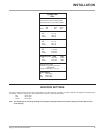
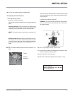
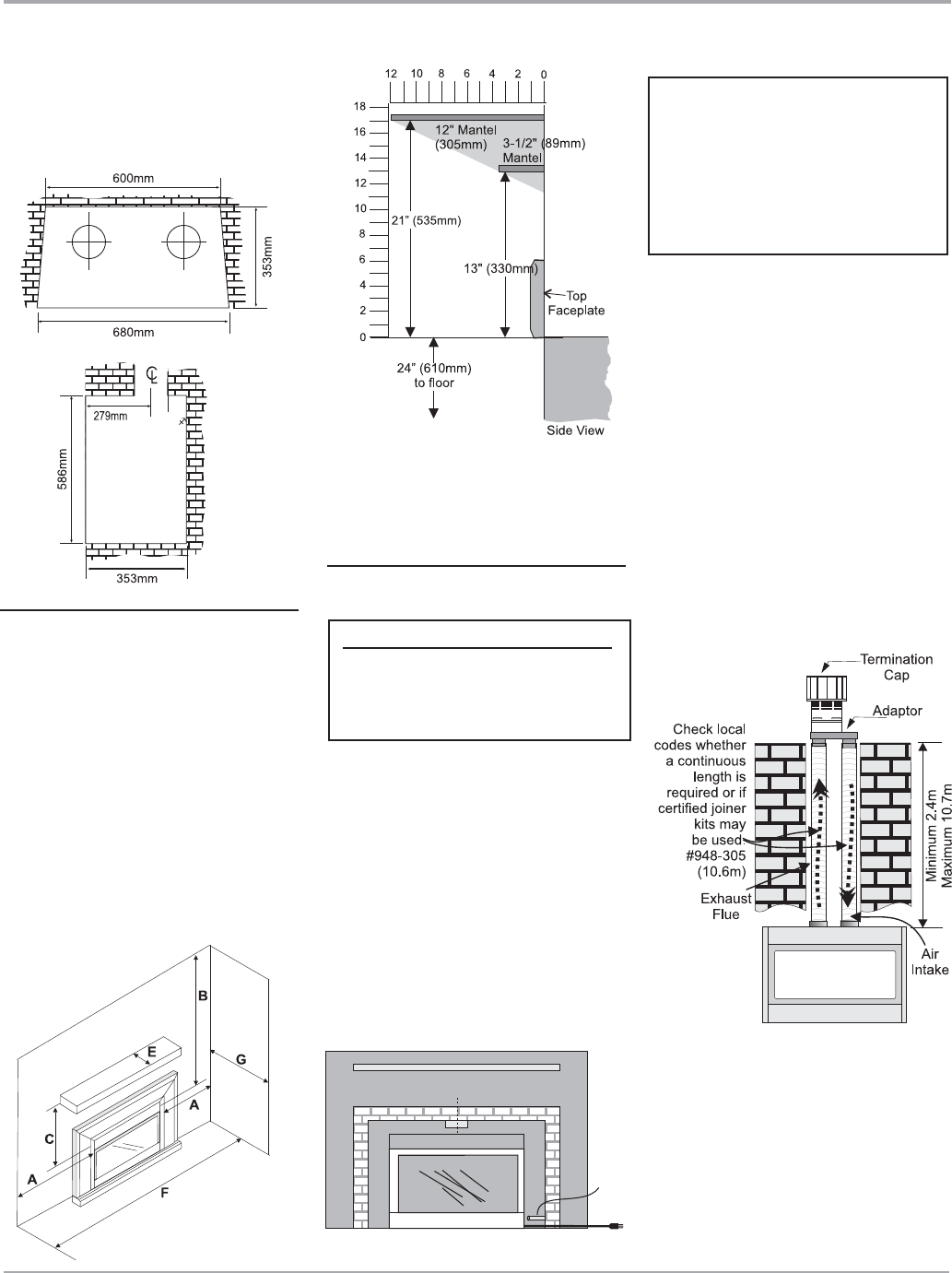
FLUEING
This appliance is designed to be attached to
two 3" (76mm) co-linear aluminium fl ex running
the full length of the chimney. The fl ue length
must be a minimum length of 8 ' (2.44m) and
a maximum of 35' (10.7m). See chart below for
minimum distances from roof. Periodically check
that the vent is unrestricted.
Masonry chimneys may take various contours
which the fl exible liner will accommodate.
However, keep the fl exible liner as straight as
possible, avoid unnecessary bending.
The Air Intake pipe must be attached to the inlet
air collar of the termination cap.
Part # Description
948-305 76mm Flex - 10.6m
46dva-gk Simpson Duravent Adaptor
46dva-vch Simpson Vertical high wind cap
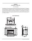
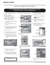
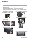
MINIMUM FIREPLACE
DIMENSIONS
The minimum fi replace dimensions for the
Regency gas space heater are shown in the
following diagrams:
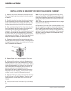
THE APPLIANCE MUST NOT
BE CONNECTED TO A
CHIMNEY FLUE SERVING A
SEPARATE SOLID FUEL
BURNING APPLIANCE AND
MUST BE TERMINATED TO
THE OUTDOORS.
Note: When installing the fl ueing, identify
the fl ues.
Mark one exhaust and one intake as
indicated on the top of the unit.