


Special offers from our partners!

Find Replacement BBQ Parts for 20,308 Models. Repair your BBQ today.

5
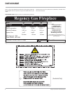
Regency IG34 Gas Inbuilt Fireplace
INSTALLATION
IMPORTANT MESSAGE
The Regency Gas Inbuilt must be installed in
accordance with these instructions. Carefully
read all the instructions in this manual fi rst.
Note: Failure to follow these instructions
could cause a malfunction of the
heater which could result in death,
serious bodily injury, and/or prop-
erty damage. Failure to follow these
instructions may also void your fi re
insurance and/or warranty.
FOR YOUR SAFETY
This appliance requires air for proper combus-
tion. Always provide adequate combustion
and ventilation air. Follow instructions and
information in the current AS5601, NZS 5262
or local codes. Consult the "authority having
jurisdiction" to determine the need for a permit
prior to starting the installation.
BEFORE YOU START
Installation is to be carried out ONLY by an
authorised person.
1) The appliance shall be installed in accord-
ance with the manufacturer's installation
instructions, local gas fi tting regulations,
municipal building codes, water supply
regulations, electrical wiring regulations,
with AS5601. (AGA gas installation code)
NZS 5262(New Zealand)
2) Installation and repair should be done
ONLY by an authorised person.
3) The appliance should be inspected before
use and at least annually by an authorised
service person. More frequent cleaning may
be required due to excessive lint from carpet-
ing, bedding material, etc. It is imperative
that control compartments, burners and
circulating air passageways of the appliance
be kept clean and free from excessive lint
from carpeting.
4) See general construction and assembly
instructions. This appliance may only be in-
stalled in a fl ued, non-combustible fi replace.
The appliance and fl ue should be enclosed
when installed or passing through a living
area, where children may come in contact
with it.
5) Always connect this space heater to a chim-
ney and fl ue to the outside of the building
envelope. Never fl ue to another room. Make
sure that the fl ue is properly sized and is
of adequate height to provide the proper
draft.
6) Inspect the fl ueing system annually for
blockage and any signs of deterioration.
7) Any safety glass removed for servicing
must be replaced prior to operating the ap-
pliance.
8) To prevent injury, do not allow anyone who
is unfamiliar with the operation to use the
fi replace.
9) Installer must mechanically attach the sup-
plied label to the inside of the fi rebox of the
fi replace into which the gas fi replace insert
is installed.
MATERIALS REQUIRED
A 240 Volt AC power cord is hooked up to the
unit. Plug 3 wire cord into a suitable receptacle.
Do not cut the ground terminal off under any
circumstances.
When connected with 240 volts, the appliance
must be electrically grounded in accordance
with local codes.
This unit is polarity sensitive and will not
operate if polarity is incorrect.
"WARNING: This fi replace has been converted
for use with a gas fi replace insert only and
cannot be used for burning wood or solid fuels
unless all original parts have been replaced,
and the fi replace re-approved by the authority
having jurisdiction."
WARNING:
Suitable for installation into a masonry
fi replace only.
INSTALLATION
CHECKLIST
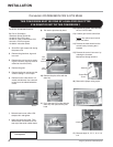
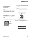
Before installing vent system ensure that the
damper plate is open and secure to prevent the
damper plate from falling down and crushing
the liner.
The FPI Gas Inbuilt is installed as listed.
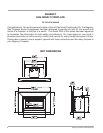
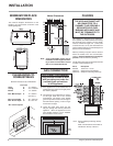
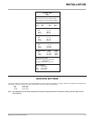
1) Check all clearances to combustibles, (Refer
to sections "Minimum Fireplace Dimensions
and Clearances to Combustibles)
2) Make the gas connection. (Refer to section
"Gas Connection")
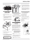
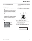
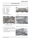
3) Install the 3" (76.2mm) fl ue liner to the sliding
connector plate. (Refer to section "Flue Liner
Installation.")
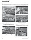
4) Slide the unit half way into the fi replace.
5) Pull the vent connector plate through the
tapered brackets and fasten to the front plate.
Refer to section "Flue Liner Installation.")
6) Slide the unit fully into the fi replace.
7) Test gas pressure (Refer to section "Gas
Pipe Pressure Testing"). Check aeration
system (Refer to section "Gas Insert Aeration
System").
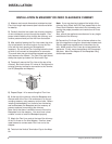
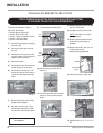
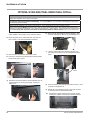
8) Install standard and optional features. Refer
to the following sections:
a. Log Set
b. Faceplate & Door Trim
c. Inner Stainless Panels
9) Final check: Before leaving this unit with the
customer, the installer must ensure that the
appliance is fi ring correctly. This includes:
a) Clocking the appliance to ensure the
correct fi ring rate.
b) Adjusting the primary air and restrictor
settings, if required, to ensure that the
fl ame does not carbon.
NOTE:
TO BE INSTALLED ON A
NON- COMBUSTIBLE FLOOR.