


Special offers from our partners!

Find Replacement BBQ Parts for 20,308 Models. Repair your BBQ today.

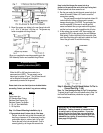
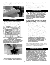
Keep in mind that the gas line access hole is on
the back of the post and the notch at the top if facing front.
Recheck plumb and allow cement to set.
2. Run the gas supply line into the post access hole (just
above the cement). Make a 90° bend to reach the
access door opening.
The gas supply line should be trenched at least 18
inches below the surface of the ground to prevent
damage from digging. CAUTION: The gas supply line
must be regulated (in the case of natural gas that
means connected after your gas meter and regulator)
and that you have an easily accessible shut-off valve.
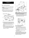
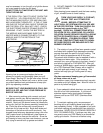
3. At the access door connect a 3/8" flare coupling (not
supplied by PGS) to the gas supply line and Stainless
Steel tubing. Position the tubing in the top notch of the
post. Bend the tubing at the top end to match the Feed
Line of the grill valve. Do not kink the tubing.
3. Mount the grease cup holder to the rear flange hole with
a ¼ - 20 x ¾" bolt and ¼-20 Kep nut. The grease cup
holder is su
pp
lied with the
g
rill head.
When you complete the mounting assembly go to the
Grill Assembly Section and assemble the grill head.
In-Ground Mounting
Assembly Instructions (48PP)
Either the A30 or A40 may be mounted on a
permanent post (48PP). The gas supply can be
natural gas or system LP gas. The grill head should
not be attached to the post until the post is
permanently cemented in the ground.
12
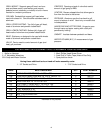
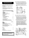
Please check to be sure that all parts are included before
proceeding. Contact your dealer if any parts are missing.
Parts Quantity
4' Post 1
Post access door 1
28” Stainless Steel Tubing 1
Stainless Steel Grease Cup 1
Stainless Grease Cup Holder 1
¼ - 20 x ¾" Hex Head Bolts 3
¼ - 20 Kep Nuts 3
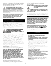
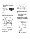
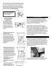
Step 1: In-Ground Mounting Installation (Fig. 9)
1. Dig a posthole about 8 inches wide by 2 feet deep.
Caution: Locate the hole so that the mounted grill
head has a clearance of 18 inches away from any
combustible object or surface; back, left or right.
Center the post in the hole and plumb it. Pour in
cement (gravel) up to the gas line access hole.
Step 2: Attaching The Grill Head Bottom To The In-
Ground Post (Fig. 7 & 8)
Note: For Tube Bending see Page 24 Fig 47 in instructions.
To attach the grill head to the post please refer to Step 3 of
the Deck/Patio installation procedures on page 14 and
follow instructions.
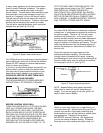
SPECIAL NOTE REGARDINIG TUBE
BENDING: Tubing is made of a material that
is easily bent to correct position. If you are
doing this for the first time, you may wish to
loosely pack the tubing with sand to give the
sidewalls the rigidity to bend without kinking
(see page 24 figure 49)