


Special offers from our partners!

Find Replacement BBQ Parts for 20,308 Models. Repair your BBQ today.

7
www.napoleonreplaces.com
ENCLOSURES FOR LP GAS SUPPLY SYSTEMS
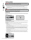
WARNING! During the inial purging and subsequent lighngs, NEVER allow gas valve to remain in
the “Open” posion without rst placing and igning the restarter.
If you build an enclosure for an LP gas cylinder, follow these recommended specicaons. You must also
follow local codes.
• Enclosures for LP gas supply cylinders shall be venlated by openings at the level of the cylinder valve and
at oor level. The eecveness of the opening(s) for purposes of venlaon shall be determined with the
LP gas supply cylinder(s) in place. This shall be accomplished by one of the following:
One side of the enclosure shall be completely open;
OR
For an enclosure having four sides, a top and boom:
a) At least two venlaon openings at cylinder valve level shall be provided in the side wall, equally sized,
spaced at 180 degrees (3.14 rad), and unobstructed. Each opening shall have a total free area of not less than
½ square inch per pound (3.2 sq. cm/kg) of stored fuel capacity and not less than a total free area of 10 square
inches (64.5 sq. cm).
b) Venlaon opening(s) shall be provided at oor level and shall have a total free area of not less than ½ inch
per pound (3.2 sq. cm/kg)
of stored fuel capacity and not less than a total free area of 10 square inches
(64.5
sq. cm). If venlaon openings at oor level are in a side wall, there shall be at least two openings. The
boom of the openings shall be at oor level and the upper edge no more than 5 inches (127mm) above the
oor. The openings shall be equally sized, spaced at 180 degrees (3.14 rad) and unobstructed.
c) Every opening shall have minimum dimensions so as to permit the entrance of a 1/8 inch (3.2mm) diameter
rod.
• Cylinder valves shall be readily accessible for hand operaon. A door on the enclosure to gain access to
the cylinder valve is acceptable, provided it is
non-locking and can be opened without the
use of tools.
• There shall be a minimum clearance of 2 inches
(50.8mm) between the lower surface of the
oor of the LP gas supply cylinder enclosure
and the ground.
• The design of the enclosure shall be such
that (1) the LP gas supply cylinder(s) can be
connected, disconnected and the connecons
inspected and tested outside the cylinder enclosure; and (2) those connecons which could be disturbed
when installing the cylinder(s) in the enclosure can be leak tested inside the enclosure.
• Be certain to mount or set the LP gas cylinder on a at surface and restrain it to prevent it from pping.
• Purge the gas supply line of any trapped air prior to the rst ring of the unit.
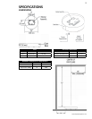
Natural Gas
Supply Line
(not supplied)
Propane Regulator
Hose
Manual Gas
Valve (on/off)
QCC1
Cylinder Retaining
Bracket
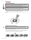
CYLINDER RETAINING BRACKET
1. Fasten the bracket to the boom of the propane bole using bolt
and nut supplied.
2.
Tighten the lag screw into the mounng surface leaving
approxi
mately
1
/
4
” of thread above the surface.
3. Slide propane bole into posion so that the bracket slides under
the head of the lag screw.
4. Tighten the lag screw onto the bracket.
5. For fastening to a concrete surface a concrete anchor will be required.
(Not supplied)
S
E
E
T
H
R
U