


Special offers from our partners!

Find Replacement BBQ Parts for 20,308 Models. Repair your BBQ today.

16
W415-0484 / A / 07.26.06
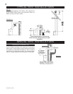
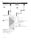
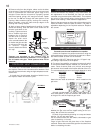
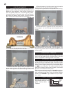
Vertical terminations may display a very active flame. As
this appearance is not desirable, the vent exit must be
restricted using restrictor plate, W500-0205. This reduces
the velocity of the exhaust gases, slowing down the flame
pattern and creating a more traditional appearance.
Remove the two screws on either side of the exhaust collar
inside the firebox. Install the plate as shown. The plate is
adjustable depending on the required restriction. Replace
the screws.
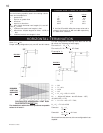
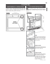
Proceed once the vent installation is complete.
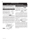
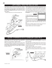
1. Move the fireplace into position and secure using the
nailing tabs and/or secure to the floor through the ¼"diam-
eter holes located at either end of the base.
2. Route a 3/8" N.P.T. black iron gas line, 1/2" type-L cop-
per tubing or equivalent to the fireplace.
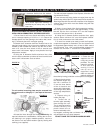
3. For ease of accessibility, an optional remote wall switch
or millivolt thermostat may be installed in a convenient lo-
cation. Route 2-strand (solid core) millivolt wire through
the electrical hole located at the bottom left side of the unit.
The recommended maximum lead length depends on wire
size:
WIRE SIZE MAX. LENGTH
14 gauge 100 feet
16 gauge 60 feet
18 gauge 40 feet
Attach the two leads to terminals 1 and 3 located on the
gas valve.
4. Install rigid black pipe, 1/2" type-L copper tubing or, if
local codes permit, a 3/8" flex connector and shutoff valve
to the gas line and the fireplace gas valve.
Seal and tighten securely. An adapter fitting is required
between the gas valve and the copper tubing or flex con-
nector. Do not kink flex connector.
5. Check for gas leaks by brushing on a soap and water
solution. Do not use open flame.
Do not connect either the wall switch, thermostat or gas
valve to electricity (110 volts).
Purge all gas lines with the glass door of the fireplace
removed. Assure that a continuous gas flow is at the burner
before re-installing the door.
FIGURE 26
FIGURE 25
GAS INSTALLATION
RESTRICTING VERTICAL VENTS
FIGURE 23
FIREPLACE VENT CONNECTION
RESTRICTOR PLATE
TOP OF THE
FIREBOX
FLUE COLLAR
FIGURE 24
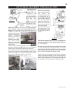
STORM
COLLAR
FLASHING
CAULKING
WEATHER
SEALANT
2”
AIR INLET
BASE
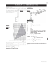
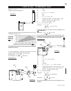
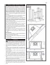
5. Remove nails from the shingles, above and to the sides
of the chimney. Place the flashing over the air terminal and
slide it underneath the sides and upper edge of the
shingles. Ensure that the air terminal is properly centred
within the flashing, giving a 3/4" margin all around. Fasten
to the roof. Do not nail through the lower portion of the
flashing. Make weather-tight by sealing with caulking.
Where possible, cover the sides and top edges of the
flashing with roofing material.
6. Apply a heavy bead of weatherproof caulking 2 inches
above the flashing. Slide the storm collar around the air
terminal and down to the
caulking. Tighten to ensure
that a weather-tight seal
between the air terminal
and the collar is achieved.
Attach the other storm
collar centred between the
air intake vent pipe and the
air exhaust slots onto the
air terminal. Tighten
securely. Attach the vertical
rain cap.
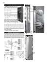
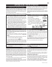
Spacers are attached to the exhaust liner at
predetermined intervals to maintain a 1-1/4" air gap to
the air intake vent pipe. These spacers must not be
removed.
1. Install the 5 inch diameter aluminium flexible liner to
the fireplace. Secure with 3 screws and flat washers. Seal
the joint and screw holes using the high temperature seal-
ant Mill Pac.
2. Install the 8 inch diameter aluminium flexible liner to
the fireplace. Attach and seal the joints.
FIGURE 22