


Special offers from our partners!

Find Replacement BBQ Parts for 20,308 Models. Repair your BBQ today.

15
W415-0484 / A / 07.23.06
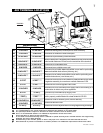
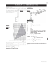
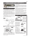
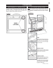
INNER FLEX
LINER
OUTER
FLEX
LINER
INNER
SLEEVE
HIGH
TEMPERATURE
SEALANT
AIR
TERMINAL
CONNECTOR
FIGURE 18
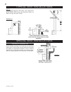
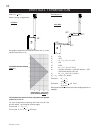
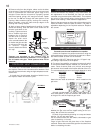
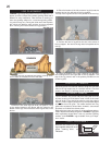
A VENT SHIELD MUST BE USED IF THE WALL TERMINAL IS
INSTALLED ON COMBUSTIBLE, EXTERIOR SURFACES.
1. Cut or frame a hole in an exterior wall with a minimum
oval or rectangle opening of 10½"w x 11 ½"h. Secure the
firestop spacer over the opening to the interior wall, ensur-
ing 2" clearance above the vent pipe opening.
2. Stretch the 5" diameter aluminum flexible liner to the
required length taking into account the additional length
needed for the finished wall surface. Slip the liner a mini-
mum of 2" over the inner sleeve of the air terminal and
secure with 3 #8 screws. Apply a heavy bead of the high
temperature sealant.
3. Using the 8" diameter flexible aluminum liner, slide
over the outer combustion air sleeve of the air terminal and
secure with 3 #8 screws. Seal as before.
The air terminal mounting plate may be recessed into
the exterior wall or siding by 1½", the depth of the return
flange.
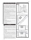
5. Apply a heavy bead of the high temperature sealant,
Mill Pac, to the inside of the 5" liner approximately 1" from
the end. Slip the liner a minimum of 2" over the fireplace
vent collar and secure with 3 #8 screws.
6. Using the 8" diameter flexible aluminium liner, apply
sealant, slide a minimum of 2" over the fireplace combus-
tion air collar and secure with 3 #8 screws.
7. If more liner needs to be used to reach the fireplace,
couple them together as illustrated. The vent system must
be supported approximately every 3 feet for both vertical
and horizontal runs. Use noncombustible strapping to
maintain the minimum 1" clearance to combustibles.
FIGURE 19
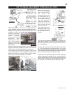
HORIZONTAL AIR TERMINAL INSTALLATION
VERTICAL AIR TERMINAL INSTALLATION
4. Insert the liners through the firestop maintaining the
required clearance to combustibles. Holding the air termi-
nal (lettering in an upright, readable position), secure to
the exterior wall and make weather tight by sealing with
caulking (not supplied).
Use only approved aluminum flexible liner kits marked:
"Wolf Steel Approved Venting" as
identified by the stamp only on the 8”
outer liner.
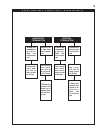
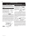
USING FLEXIBLE VENT COMPONENTS
For safe and proper operation of the fireplace, follow the vent-
ing instructions exactly.
All inner exhaust and outer intake vent pipe joints may be
sealed using either Red RTV high temp silicone sealant or
Black high temp Mill Pac with the exception of the fireplace
exhaust flue collar which must be sealed using Mill Pac
(not supplied).
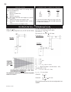
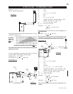
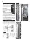
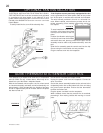
1. Fasten the roof
support to the roof
using the screws
provided. The roof
support is optional.
In this case the
venting is to be
adequately
supported using
either an alternate
method suitable to
the authority having jurisdiction or the optional roof support.
2. Stretch the exhaust to
the required length. Slip
the liner a minimum of
2" over the inner sleeve
of the air terminal and
secure with 3 #8 screws.
Seal using a heavy bead
of the high temperature
sealant.
3. Repeat using air
intake vent pipe.
4. Thread the air
terminal pipe assembly
down through the roof.
The air terminal must be
located vertically and
plumb. Attach the air
terminal assembly to the
roof support, ensuring that a minimum 16" of air terminal
will penetrate the roof when fastened.
DO NOT CLAMP THE FLEXIBLE ALUMINIUM LINER.
ROOF SUPPORT
FIGURE 20
FIGURE 21