


Special offers from our partners!

Find Replacement BBQ Parts for 20,308 Models. Repair your BBQ today.
W415-0638 / 04.24.08
6
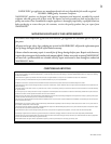
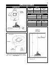
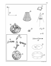
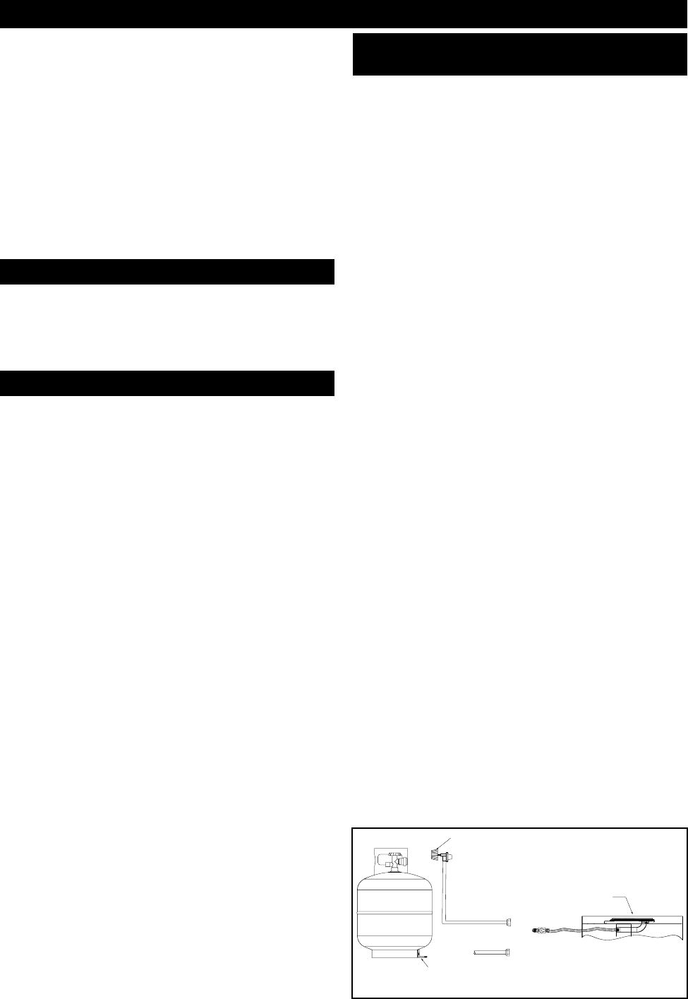
Natural Gas
Supply Line
(not supplied)
Propane Regulator
Hose
Manual Gas
Valve (on/off)
QCC1
Tank Retaining
Bracket
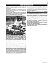
INSTALLATION
The log set and the burner assembly are shipped together.
Remove the gas log set and burner assembly and check for
damage. DO NOT install damaged components. The logs are
fragile use care when handling.
Place the Patiofl ame on a level/secure surface in desired
location. This location must be adjacent to the gas supply
line or cylinder.
NOTE: Minimum clearances to combustible construction must
be maintained. ( See Page 5)
You must have clear and easy access to the on/off valve
AFTER the appliance is installed and connected to the gas
supply in order to safely turn off the burner.
THE ON/OFF GAS VALVE IS USED TO TURN THE
BURNER ON AND OFF.
Connect the incoming gas supply line to the on/off gas valve
of the appliance. Make certain ALL gas connections are tight,
turn the on/off valve at the unit slowly to the on position and
use soap water to test for leaks.
DO NOT USE AN OPEN FLAME.
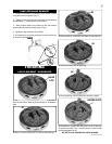
1. Attach tank retaining bracket supplied to the base of the
cylinder. Then secure to the surface to which it sits. Cylinder
should be on a level surface.
2. Make sure tank valve is in its full off position. (Turn clock-
wise to stop).
3. Check tank valve features to ensure it has proper external
mating threads. (Tank Valve Marked: USE WITH TYPE 1)
4. Inspect hose shipped with the unit for damage. Never at-
tempt to use damaged or plugged equipment. See your local
LP Gas Dealer for repairs.
5. After inspecting the LP hose shipped with the unit, connect
the end with the female fi tting on the hose to the male fi tting
on the on/off gas valve at the end of the fl ex tube. Tighten
fi ttings using 2 wrenches.
6. When connecting regulator assembly to the tank valve,
hand tighten black QCC1 nut clockwise to a positive stop.
DO NOT use a wrench to tighten. Use of a wrench may dam-
age the quick closing coupling nut and result in a hazardous
condition.
7. Locate the hose out of pathways where people may trip
over it or in areas where the hose may be subject to acci-
dental damage.
8. Open tank valve fully (counter-clockwise). Turn the on/off
valve at the unit slowly to the on position and use a soapy
water solution to check all connections for leaks before at-
tempting to light the appliance. If a leak is found, turn tank
valve off and do not use the appliance until repairs can be
made.
NATURAL GAS
LP GAS
ENCLOSURES FOR LP GAS SUPPLY
SYSTEMS
If you build an enclosure for an LP gas cylinder, follow these
recommended specifi cations. You must also follow local
codes.
Enclosures for LP gas supply cylinders shall be ventilated by
openings at the level of the cylinder valve and at fl oor level.
The effectiveness of the opening(s) for purposes of ventila-
tion shall be determined with the LP gas supply cylinder(s) in
place. This shall be accomplished by one of the following:
1. One side of the enclosure shall be completely open;
or
2. For an enclosure having four sides, a top and bottom:
a) At least two ventilation openings at cylinder valve level
shall be provided in the side wall, equally sized, spaced at
180 degrees (3.14 rad), and unobstructed. Each opening
shall have a total free area of not less than ½ square inch per
pound (3.2 sq. cm/kg) of stored fuel capacity and not less than
a total free area of 10 square inches (64.5 sq. cm).
b) Ventilation opening(s) shall be provided at fl oor level and
shall have a total free area of not less than ½ inch per pound
(3.2 sq. cm/kg) of stored fuel capacity and not less than a
total free area of 10 square inches (64.5 sq. cm). If ventilation
openings at fl oor level are in a side wall, there shall be at least
two openings. The bottom of the openings shall be at fl oor
level and the upper edge no more than 5 inches (127mm)
above the fl oor. The openings shall be equally sized, spaced
at 180 degrees (3.14 rad) and unobstructed.
c) Every opening shall have minimum dimensions so as to
permit the entrance of a 1/8 inch (3.2mm) diameter rod.
3. Cylinder valves shall be readily accessible for hand opera-
tion. A door on the enclosure to gain access to the cylinder
valve is acceptable, provided it is non-locking and can be
opened without the use of tools.
4. There shall be a minimum clearance of 2 inches (50.8mm)
between the lower surface of the fl oor of the LP gas supply
cylinder enclosure and the ground.
5. The design of the enclosure shall be such that (1) the LP
gas supply cylinder(s) can be connected, disconnected and
the connections inspected and tested outside the cylinder
enclosure; and (2) those connections which could be disturbed
when installing the cylinder(s) in the enclosure can be leak
tested inside the enclosure.
6. Be certain to mount or set the LP gas cylinder on a fl at
surface and restrain it to prevent it from tipping.
Purge the gas supply line of any trapped air prior to the fi rst
fi ring of the unit.
WARNING: During the initial purging and subsequent
lightings, NEVER allow gas valve to remain in the
"Open" position without fi rst placing and igniting the
fi restarter.