


Special offers from our partners!

Find Replacement BBQ Parts for 20,308 Models. Repair your BBQ today.
4
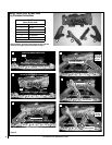
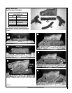
NOTE: DIAGRAMS & ILLUSTRATIONS ARE NOT TO SCALE.
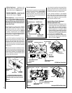
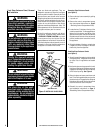
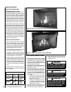
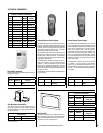
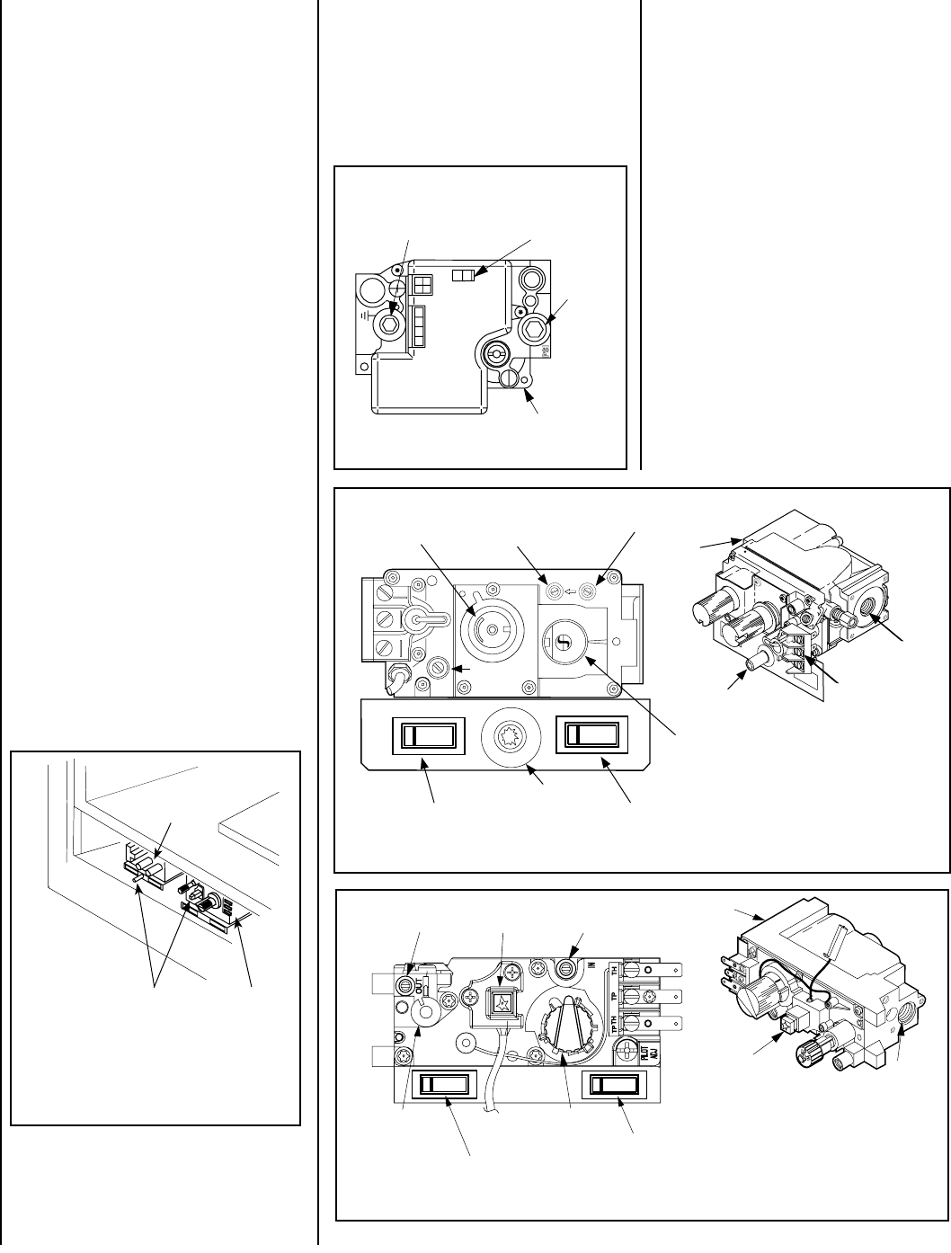
Figure 2
Sit and Honeywell Millivolt Gas Valve
Showing Piezo Igniter Location (Each Unit is
Equipped with Only One of these Gas Valves)
Millivolt Appliances - Appliances with
Millivolt systems will be fitted with the gas
control valve shown in Figures 4 or 5.
Electronic Appliances - Appliances with
electronic systems will be fitted with the
electronic valve shown in
Figure 3.
Millivolt Appliances - To light millivolt appli-
ances refer to the detailed lighting instructions
found on Pages 18 & 19 . Millivolt appliance
lighting instructions may also be found on the
pull out lighting instruction labels attached to
the gas control valve.
Millivolt appliances are fitted with an OFF/ON
Rocker Switch located behind the control
compartment access door, below the appli-
ance front glass enclosure panel (see Figure 2
for location). Once the pilot is lit, the OFF/ON
rocker switch will control the appliance OFF/ON
burner operation. To operate: Toggle the switch
between its ON and OFF positions.
If your millivolt appliance is equipped with an
optional remote switch kit (wall switch, remote
control or wall thermostat) and the pilot is lit,
the appliance main burner may be turned on
and off using the optional switch. When using
an optional remote switch, turn off the standard
OFF/ON switch.
Note: To prevent excessive resistance in burner
circuit (which can cause burner operation prob
-
lems), only one burner control switch should be
wired to valve. Therefore, if an optional control
switch is installed, the standard Off/On switch
and wires should be removed.
SIT Gas Valve
Shown with control
compartment door
removed
Piezo Igniter
Honeywell
Gas Valve
If your electronic appliance is equipped with an
optional remote wall switch or remote control kit
the appliance main burner may be turned on and
off with the wall switch or remote control.
If your electronic appliance is not equipped
with a wall switch or remote control, the main
burner must be turned off and on with the gas
control switch. Toggle the switch from ON to
OFF to operate the main burner .
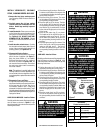
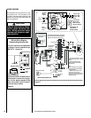
Variable Flame Height Adjustment
(Millivolt Appliances only)
1. All Millivolt appliances are equipped with a
variable gas control valve. Flame height for
these models may be adjusted through a
range between fixed low and high settings
while the appliance is in operation. Adjust
the flame height as desired after lighting the
appliance by rotating the variable adjustment
control knob (HI/LO) located on the front of
the valve (refer to
Figures 4 & 5 ).
2. During the first initial burns of these appli-
ances, there will be some odor emitted (see
Burn-In Period on Page 3 ).
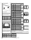
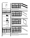
Honeywell Millivolt Gas Valve
Figure 5
O
N
O
F
F
P
I
L
O
T
L
O
H
I
OFF
ON
OFF
ON
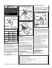
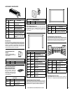
Figure 3
Optional Blower OFF/ON
Rocker Switch
SIT Millivolt Gas Valve
Gas
Outlet
Gas
Inlet
Pilot Adjustment
Screw
Terminals
TPTH,TP & TH
Figure 4
H
I
L
O
W
H
T
P
T
H
T
P
T
P
I
L
O
T
P
I
L
O
T
O
N
ti
O
F
F
IN
OUT
OFF
ON
OFF
ON
HI/LO Variable
Flame Height
Adjustment
Manifold Pressure Tap
Inlet Pressure Tap
Piezo Igniter
Main Gas
Control Knob
OFF/PILOT/ON
Piezo Igniter
Optional Burner OFF/ON
Rocker Switch
Piezo Igniter
Optional Blower OFF/ON
Rocker Switch
Optional Burner OFF/ON
Rocker Switch
HI/LO Variable
Flame Height
Adjustment
Main Gas
Control Knob
OFF/PILOT/ON
Manifold Pressure
Tap
Piezo Igniter
Inlet Pressure Tap
Gas
Outlet
Gas
Inlet
Honeywell Electronic Gas Valve
F
F
O
N
I
P
S
I
NO
L
O
R
T
N
O
C
G
I
N
T
I
ER
Manifold Pressure
Port
ON/OFF Switch
Inlet
Pressure
Port
Electronic Gas
Control Valve
Electronic Appliances -
To light electronic appliances refer to the detailed
lighting instructions found on
Pages 20 & 21
of these instructions. Electronic appliance
lighting instructions may also be found on the
pull out lighting instruction labels attached to
the gas control valve.