


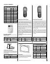
Special offers from our partners!

Find Replacement BBQ Parts for 20,308 Models. Repair your BBQ today.
3
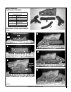
NOTE: DIAGRAMS & ILLUSTRATIONS ARE NOT TO SCALE.
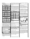
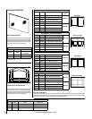
Burner Orifice Sizes
Elevation 0-4500 feet ( 0-1372 meters)
Model
Series
Natural
Gas
drill size
(inches)
Propane
Gas
drill size (inches)
LMDVT-3328
LMDVR-3328
#45 (.082")
*
39L66 •
1.2 mm (.048")
*
99K78 •
LMDV-3530
#44 (.086")
*
60J80 •
#55 (.052")
*
19L52 •
LMDV-4035
#37 (.104")
*
24M10 •
1/16"
(.0625")
*
21L01 •
* Standard size installed at factory
• Part /Cat. Number
Table 7
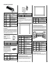
Inlet Gas Supply Pressure
(all models)
Fuel # Minimum Maximum
Natural Gas
5.0" WC
(1.24 kPa)
10.5" WC
(2.61 kPa)
Propane
11.0" WC
(2.74 kPa)
13.0" WC
(3.23 kPa)
Table 4
Burn-in Period
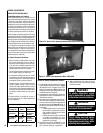
During the first few fires of this appliance there
will be some odor due to the curing of the
paint and burning off of lubricants used in the
manufacturing process.
Depending on your use, the burn-in period may
take a few hours or a few days.
KEEP YOUR HOUSE WELL VENTILATED
DURING THE CURING PROCESS. THE ODOR
AND HAZE EMITTED DURING THE CURING
PROCESS CAN BE QUITE NOTICEABLE AND
MAY SET OFF A SMOKE DETECTOR.
If an optional blower is installed, Do not turn it
on during the Burn-In period.
A white film may develop on the glass front
during the first few fires as part of the curing
process. The glass should be kept clean during
the first two weeks of use to prevent the film from
baking on (making it very difficult to remove).
See
Cleaning Glass on Page 5.
These appliances and their individual shut-off
valves
must be disconnected from the gas
supply piping system during any pressure
testing of that system at pressures
greater
than 1/2 psig (3.5 kPa).
These appliances must be isolated from the
gas supply piping system (
by closing their
individual manual shut-off valve) during any
pressure testing of the gas supply piping
system at test pressures equal to or
less than
1/2 psig (3.5 kPa).
At the time of installation, it must be determined
if the appliance needs to be derated. Contact
your local gas supplier for deration requirements
for your area.
Deration - At higher elevations, the amount of
BTU fuel value delivered must be reduced by
either using gas that has been derated by the gas
company or by changing the burner orifice to a
smaller size as regulated by the local authorities
having jurisdiction and by the (USA) National
Fuel Gas Code NFPA 54/ANSI Z223.1 - latest
edition or, in Canada, the CAN1-B149.1 and .2
codes - latest edition.
Gas Pressure -
Tables 4, 5 and 6 show the appliances' gas
pressure requirements.
Manifold Gas Supply Pressure
(millivolt models)
Fuel # Low High
Natural
Gas
(Lo) 2.2" WC
(.55 kPa)
(Hi) 3.5" WC
(.87 kPa)
Propane
(Lo) 6.3" WC
(1.57 kPa)
(Hi) 10.0" WC
(2.49 kPa)
Table 5
Manifold Gas Supply Pressure
(electronic models)
Fuel # Fixed
Natural Gas
3.5" WC
(.87 kPa)
Propane
10.0" WC
(2.49 kPa)
Table 6
Test gauge connections are provided on the
front of the millivolt gas control valve, identified
IN for the inlet and OUT for the manifold side
(see
Figures 4 or 5 on Page 4). A 1/8" NPT
Test gauge connection is provided at the inlet
and outlet (manifold) ports on the electronic gas
control valve (see
Figure 3 on Page 4).
Orifice Sizes - Sea Level to High Altitude
(All Models): These appliances are tested and
approved for installations at elevations of 0-4500
feet (0-1372 meters) above sea level using the
standard burner orifice sizes (marked with an
"*" in
Table 7).
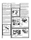
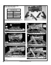
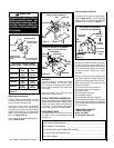
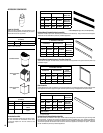
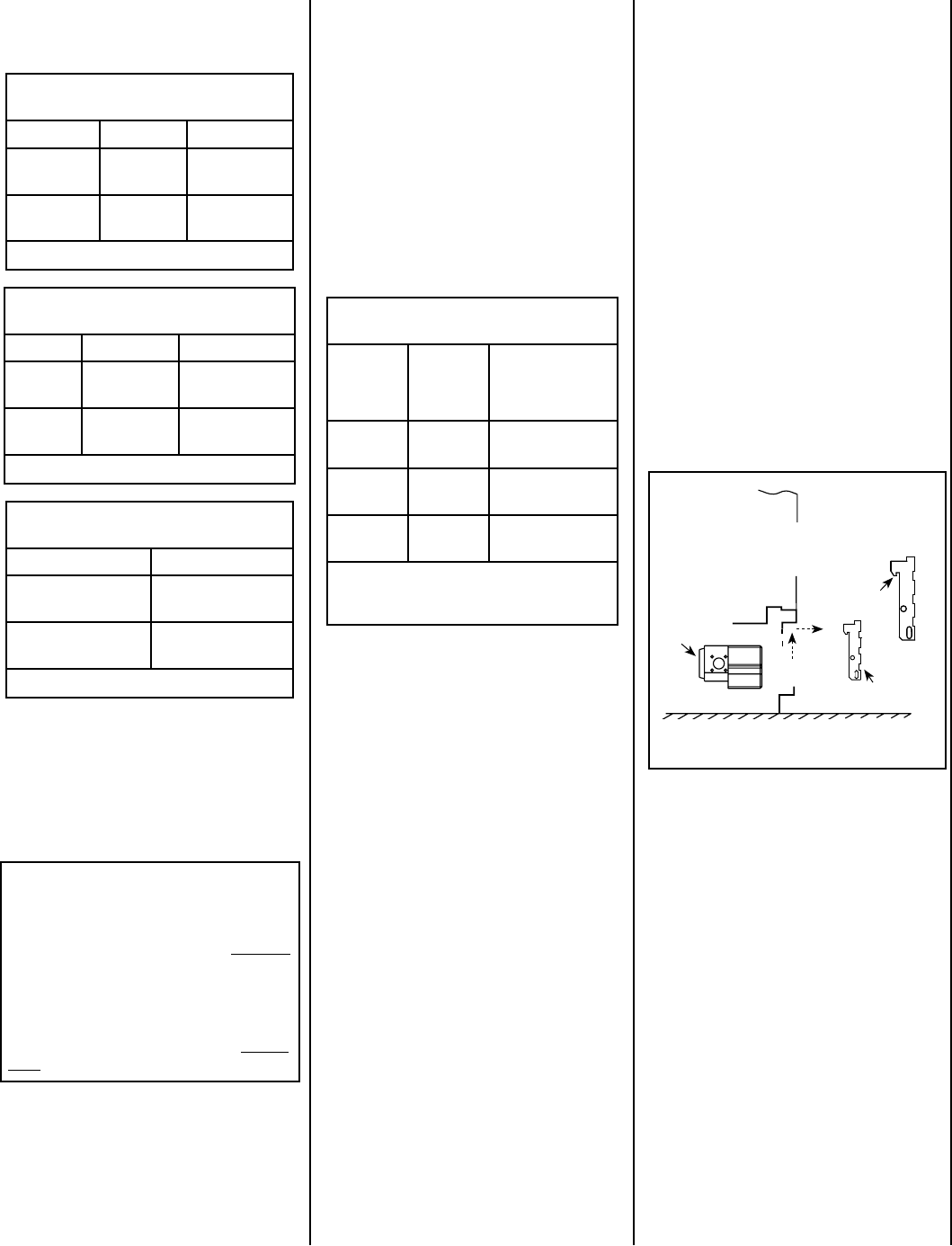
Gas Controls/Control Compartment
Access
The gas controls can be found behind the control
compartment access door.
Removing Control Compartment Door:
Open the door by gently liftint it upward until the
hook catches on boths sides clear the locating
slots. Then pull door out to remove.
On millivolt systems, the piezo igniter, HI/LO
flame adjustment knob, and pilot and main
gas OFF/ON control knob are located below
the glass panel enclosure. The gas valve for
electronic systems is also located below the
glass enclosure panel. See
Figure 1.
Reinstalling Control Compartment Door:
To reinstall, insert the hook catches on each side
of the door into the corresponding slots in the
control compartment opening, then gently push
forward and slide down until it locks in place.
Figure 1
OPENING CONTROL
COMPARTMENT DOOR
OPERATION AND CARE OF YOUR
APPLIANCE
The standard controls for appliance opera-
tion are located behind the panel below the
appliance front glass enclosure panel (see
Figure 1). Optional control switches are also
available (see
Page 13 - Remote Wall Switch,
Remote Control or Wall Thermostat).
Operation of millivolt and electronic gas con
-
trol systems are different. Before lighting and
operating your appliance determine if you have
a millivolt or electronic appliance. Familiarize
yourself with the gas control valve that your
appliance uses. Refer to
Figure 1 for access
to the gas control valve.
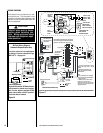
Control Valve
Lower Control
Compartment Door
Lift the Lower Control
Compartment Door
up and pull out to
remove.
Up
Out
Hook Catch