


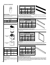
Special offers from our partners!

Find Replacement BBQ Parts for 20,308 Models. Repair your BBQ today.
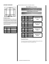
12
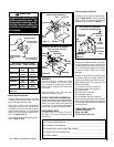
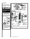
NOTE: DIAGRAMS & ILLUSTRATIONS ARE NOT TO SCALE.
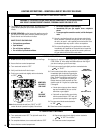
WIRING DIAGRAMS
Wiring diagrams are provided here for refer-
ence purposes only. This information is also
provided on schematics attached directly to the
appliance on a pullout panel located within the
control compartment.
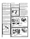
TH
TP
TH
TP
Thermopile
If any of the original wire as supplied must
be replaced, it must be replaced with Type
AWM 105
o
C - 18 gage wire.
* Optional Kits Installed - OFF/ON wall switch,
wall thermostat or remote control receiver.
Note: Turn the appliance-mounted OFF/ON
burner control switch to the OFF position if
any of these kits are installed.
Millivolt Wiring Diagram
Schematic Representation Only
Field Wired
Factory
Wired
*Optional Switch
Standard OFF/ON Switch
CAUTION
Label all wires prior to discon-
nection when servicing con-
trols. Wiring errors can cause
improper and dangerous appli-
ance operation.
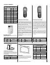
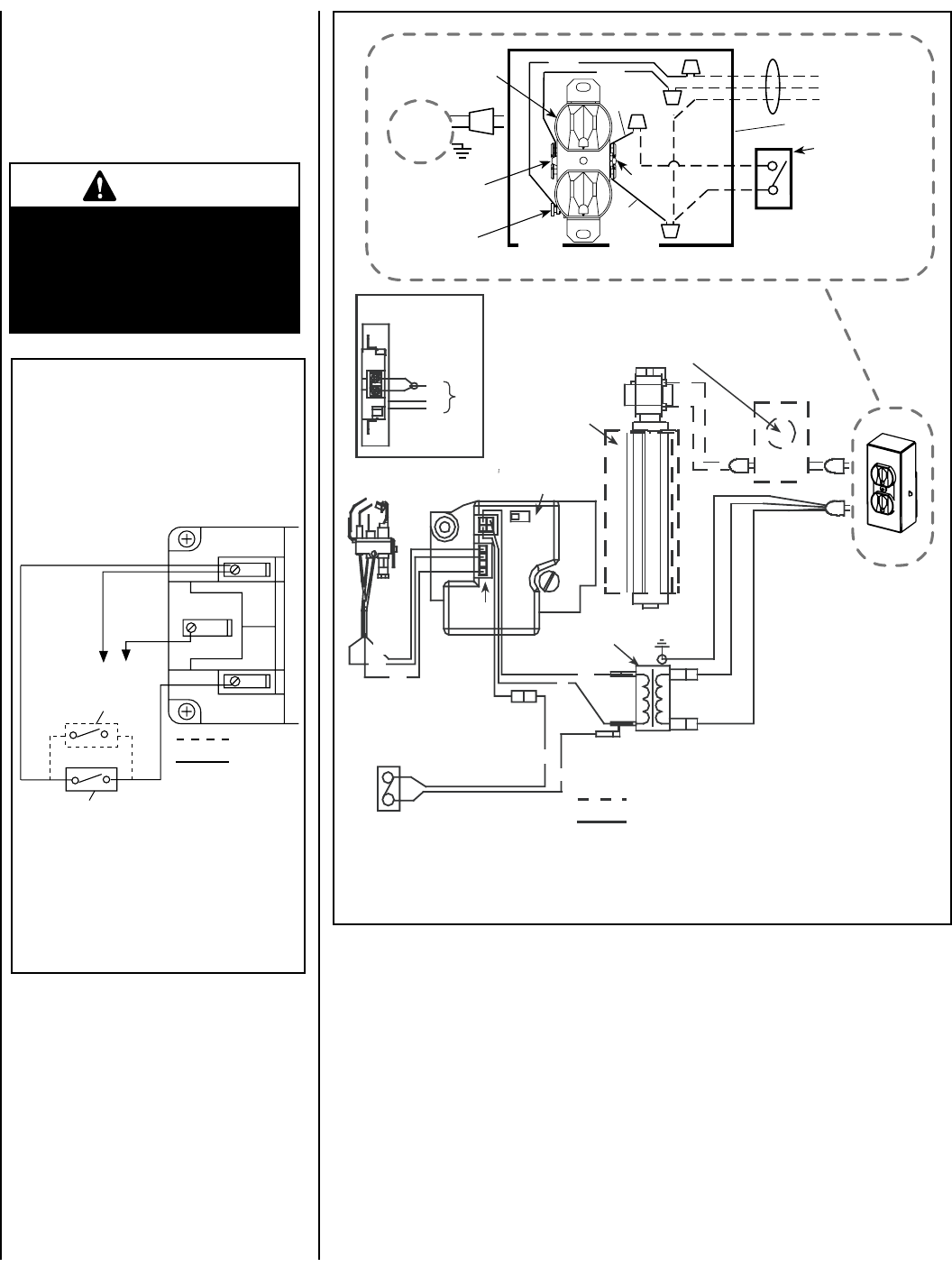
Figure 16
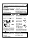
Figure 17
Electronic Wiring Diagram (Honeywell) Showing Blower Wiring for Optional FBK-100, FBK-200 & FBK-250 Kits
Schematic Representation Only
Relay Module C/W FBK-250 only. Plug blower
into J-Box receptacle for FBK-100 or FBK-200
application. See View A for J-Box wiring.
Optional Blower
*OFF/ON Switch
(Integral with
Gas Valve)
Honeywell
Electronic
Gas
Valve
120 VAC
Primary
Secondary
Optional Control Switch
Junction Box
Pilot Burner
Assembly
BL
BL
Field Wired
Factory
Wired
BK = BLACK BL = BLUE
R = RED W = WHITE
G = GREEN
BK
W
BK
BK
BL
R
GROUND
24 V
Transformer
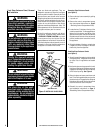
View A
J-Box Wiring when
using unit mounted
relay module.
BK
W
G
C
AV
02
1
Igniter
Connector
* Leave the OFF/ON switch, which is
integral with the gas valve, in the ON
position.
**Optional Control Switches: Wall
Switch, Wall Thermostat or Remote
Control Receiver.
Notes:
1. If any of the original wire as supplied
must be replaced, use Type AWM 105°C
- 18 gage wire ONLY.
2. 120 VAC, 60 Hz - Less than 3 Amps.
Caution: label all wires prior to
disconnection when servicing controls.
Wiring errors can cause improper and
dangerous operation.
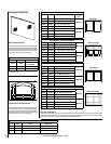
Junction Box
Tab Intact
Tab
Broken
Plug blower
into this
receptacle
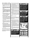
n
e
e
r
G
-
dn
u
o
r
G
* Wall-mounted
ON/ OFF Blower
Switch or Variable
Speed Control Switch.
Blower
Ground
e
ti
h
W
-
lar
t
u
e
N
120 VAC - Black
Green
Ground
Screw
White
Green
Neutral
Side of
Receptacle
Hot
Side of
Receptacle
Red
Black
J-BOX WIRING FOR
WALL SWITCH
BLOWER CONTROL