


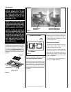
Special offers from our partners!

Find Replacement BBQ Parts for 20,308 Models. Repair your BBQ today.

8
NOTE: DIAGRAMS & ILLUSTRATIONS NOT TO SCALE.
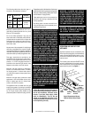
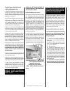
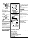
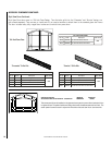
Refer to
Figure 6
and remove the front glass
enclosure panel as follows:
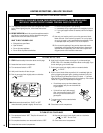
1. Remove the top bustle, and the top louver
assembly or radiant panel. Then remove the
bottom bustle.
2. Open the control compartment access panel.
To open the control compartment access panel,
actuate the spring-loaded magnetic catches
securing the panel, by gently depressing the
outer top corners of the panel until the catches
"pop" the door free, allowing it to swing out and
down to open.
3. Locate the latches at the bottom of the
firebox bottom panel. To disengage the latches
from the bottom vee-flanges of the glass en-
closure panel, reach for the handles located
towards the back of the latches and pull the
handles down towards the front of the unit.
4. Swing the bottom of the door out and raise
it slightly to lift the top flange of the door frame
away from the appliance.
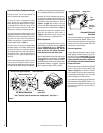
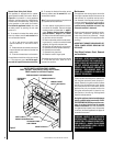
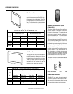
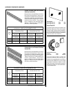
Burner Adjustments
Note -
The air shutter for the burner primary air
opening is factory-set. Do not adjust the fac-
tory-set position. The factory-set position is
shown in Figure 7.
THE GLASS DOORS OF THIS APPLIANCE MUST
ONLY BE REPLACED AS A COMPLETE UNIT AS
PROVIDED BY THE MANUFACTURER. DO
NOT ATTEMPT TO REPLACE BROKEN,
CRACKED OR CHIPPED GLASS SEPARATELY.
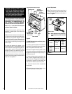
To install the front glass enclosure panel,
proceed as follows:
1. Visually inspect the gasket on the backside
of the panel. The gasket surface must be clean,
free of irregularities and seated firmly.
2. Position the glass enclosure panel in front
of the firebox opening at a 45 degree angle and
engage the top flange over the lip at the top of
the firebox opening.
3. Swing the glass enclosure panel down and
back. Ensure the gasket seats evenly as the
panel draws shut. Engage the Vee-flanges at
the bottom of the panel with the latches and
then close the latches to secure the panel.
4. Close the bottom control compartment
access panel.
5. Reinstall the top and bottom bustle, and the
top louver assembly or radiant panel.
Figure 6
Figure 7
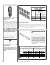
RENRUBNIAM
GNITTESRETTUHSYROTCAF
sledoM
saGlarutaN
sehcni
)mm(
enaporP
saG
sehcni
)mm(
TSVBE
FPVBE
RCVBE
LCVBE
61/1)5.1(11(61/7)
*Note - Do Not Adjust the Factory-Set Position.
The shutter opening is shown in the table
below.
Orifice
*Air Shutter
Opening
Burner
Venturi
Tube
Millivolt Shown
Glass
Enclosure
Panel
Latch
Lower Compartment Door and Hinge
Front Glass
Enclosure Panel
Firebox
Floor
Bottom Vee-flanges
(Glass Enclosure
Panel Frame)
Top Flange
(Glass Enclosure
Panel Frame)
Modesty Panel
EBVST SHOWN
WARNING: DO NOT ATTEMPT TO SUB-
STITUTE THE MATERIALS USED ON
THESE DOORS, OR REPLACE CRACKED
OR BROKEN GLASS WITH ANY MATERI-
ALS OTHER THAN THOSE PROVIDED BY
THE APPLIANCE MANUFACTURER.