


Special offers from our partners!

Find Replacement BBQ Parts for 20,308 Models. Repair your BBQ today.

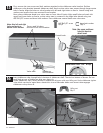
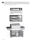
8a
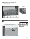
16
sideburner burner
Wing nut
electrode
Metal hose
ignitor wire
sideburner drip pan
sideburner
burner tube
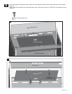
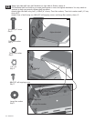
Under sideburner shelf, secure burner to sideburner drip pan with one Wing nut. Untie sideburner ignitor
A
B
valve
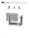
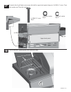
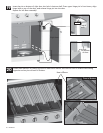
15
#8-32x3/8” screw
4mm
lock washer
Control knob
Side burner
bezel
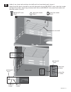
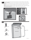
First, remove the two screws and lock washers attached to the sideburner valve bracket. Position
sideburner valve bracket beneath sideburner shelf fascia so that valve stem comes through larger center
hole in fascia. Align the holes on valve bracket with left and right holes on fascia. Attach using lock
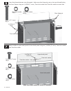
Next, place sideburner bezel over valve stem on front side of fascia. Align small holes on bezel with
upper and lower holes on fascia, so that valve stem is centered in the large hole. Attach using two
Sideburner
valve bracket
Sideburner
fascia
Valve stem
Valve stem
Screws and Washers
removed from valve bracket
Note: Use left and right
holes on fascia to
attach valve bracket
holes on fascia to
attach bezel
Note: Use upper and lower
drip pan
Burner tube engages
sideburner valve
#8-32x3/8” screw
Qty.2
Qty.2
4mm lock washer
Wing nut
Qty.1
washers and screws that were removed from bracket.
#8-32x3/8” screws and 4mm lock washers. Press sideburner control knob onto valve stem.
Install bezel with “OFF” at top.
OFF
Hi
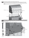
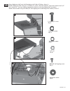
Insert sideburner tube through hole in bottom of sideburner shelf. The stud on bottom of burner fits into
small hole at rear of sideburner drip pan, shown A.
wire which was tied to metal hose. Attach this wire to electrode. Make sure burner tube engages
sideburner valve, shown B.
24 • 464224411