


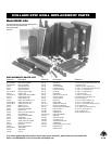

Special offers from our partners!

Find Replacement BBQ Parts for 20,308 Models. Repair your BBQ today.
E-4
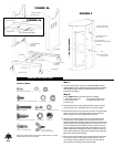
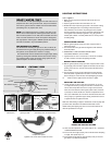
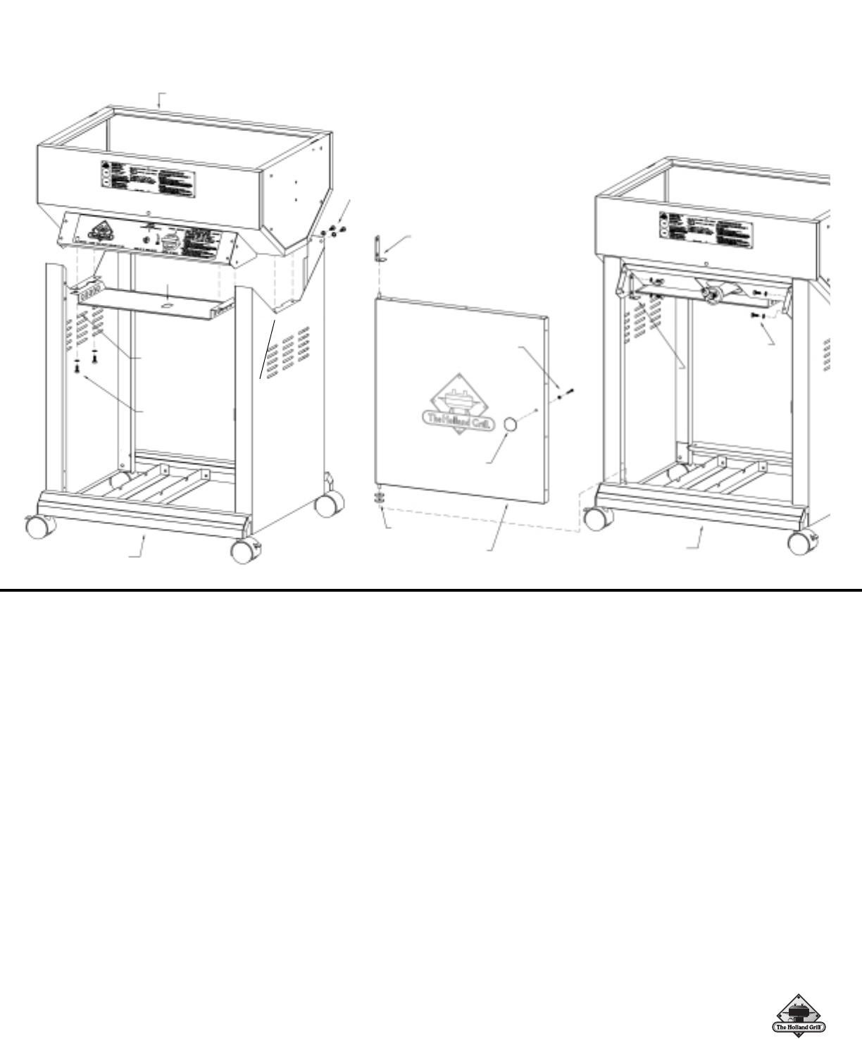
FIGURE 4a
Step 3.
Refer to Figure 3. Select the following items:
1. grill bottom assembly
2. bucket bracket
3. electrode
With the grill bottom assembly sitting upright on one end, locate the 1/4
inch diameter hole and slot close to the drain pipe hole.Insert the buck-
et hanger bracket in the slot as shown in Figure 3 and secure with 10-
24 x 1/2 Phillips head screw and lock washer.Tighten completely.
Now insert electrode into hole and secure tightly with 8-32 screw and
lock washer. Next, loosen the two 1/4-20 hex bolts shown to prepare for
the next step. DO NOT REMOVE THEM!
Step 4.
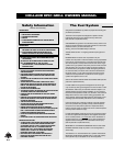
Refer to Figure 4a and Figure 4b.Select the following items:
1. grill bottom assembly 5. door pivot bracket
2. cabinet assembly 6. door knob
3. tank heat shield 7. washer/spacer (2)
4. door assembly
Figure 4a Place the grill bottom assembly onto the cabinet base
assembly.Secure the right side only at this time with 1/4-20 x 5/8 hex
head bolts and, lock washers as shown.Do not tighten at this time.
Select the tank heat shield and slide it under the two bolts that you
loosened in the previous step. Be sure the obround cutout aligns with
the electrode and route the electrode wire through it. Lift the other end
of the tank heat shield up to the flange under the grill body as shown.
Now fasten both sides securely with 1/4-20 x 5/8 hex head bolts and
lock washers.
Now bolt upper rear flange of cabinet sides to rear of grill bottom
assembly as shown. Use 1/4-20 x 1/2 hex head bolts and lock wash-
ers.Tighten completely. Repeat for opposite side.
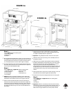
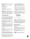
Figure 4b Using a Phillips screwdriver, remove the control panel.
Attach door knob to door panel using 10-24 x 3/8 Phillips screw and
lock washer as shown.
Select the door pivot bracket, washer/spacers and door panel assem-
bly.Slide 2 washer/spacers onto the lower pivot pin of the door assem-
bly.Now insert lower pivot pin with the washer/spacers on it into the
hole in the top surface of the lower valance.Make sure the
washer/spacers do not fall off the pin. Place the door pivot bracket onto
the upper door pivot pin.Now bolt the door pivot bracket to the control
panel bracket as shown using 1/4-20 x 5/8 hex head bolt and lock
washers.
Fasten opposite side of control panel to cabinet side using 1/4-20 x 5/8
hex head bolt and lock washers.Tighten both sides securely.
Re-attach the control panel and plug electrode wire into rotary igniter.
Step 5.
Refer to Figure 5a and Figure 5b.Select the following items:
1. grill lid assembly
2. hinges
3. lid stops (2)
Figure 5a Select one of the lid stops.Insert the end of the lid stop
with the slot in it into the slot in the body bottom end panel. Insert a 10-
24 x 1/2 carriage bolt into the square hole in the bottom end panel.
Make sure the bolt goes inside the slot of lid stop. Secure with flat
FIGURE 4b
❍
❍
❍
❍
❍
❍
❍
❍
❍
❍
❍
Cabinet Assembly
1/4 - 20 Hex Nut
1/4 Lock Washer
(both sides)
Route electrode wire
through obround hole
Bottom Assembly
1/4 - 20 x 5/8” Hex bolt
(both sides)
Secure right
side first
1/4 - 20 Hex Bolt
1/4 Lock Washer
(both sides)
Door Pivot Bracket
10 - 24 x 3/8
Phillips Screw
and Lock Washer
Knob
Door Assembly
Washer / Spacers
Cabinet Assembly
1/4 - 20 x 1/2
Hex Bolt and
Lock Washer
(both sides)
Upper Door
pivot bracket
mounting
location