


Special offers from our partners!

Find Replacement BBQ Parts for 20,308 Models. Repair your BBQ today.

29Heat & Glo LifeStyle Collection • Twilight-II-B • 2108-900 Rev. M • 11/08
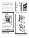
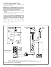
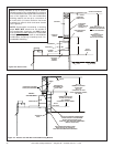
F. Wall Switch Installation for Fan (Optional)
If the box is being wired to a wall mounted switch for use
with a fan (See Figure 9.5):
• The power supply for the appliance must be brought into
a switch box.
• The power can then be supplied from the switch box to the
appliance using a minimum of 14-3 with ground wire.
• At the switch box connect the black (hot) wire and red
(switch leg) wire to the wall switch as shown.
• At the appliance connect the black (hot), white (neutral)
and green (ground) wires to the junction box as shown.
• Add a 1/4 in. insulated female connector to the red (switch
leg) wire, route it through the knockout in the face of the
junction box, and connect to the top fan switch connector
(1/4 in. male) as shown.
Red
Switch
Switch Box
Red
Black
Black
Green
Green
White
Power
Supply
Wires
White
Red
Black
Green
White
Minimum 14-3 AWG
with Ground
Junction Box
Knockout
Figure 9.5 Junction Box Wired to Wall Switch or BC10
GREEN WIRE
INSIDE BOX
14/2WG
COPPER GROUND
ATTACHED TO GRN SCREW
WITH GRN WIRE
BLK
WHT
WHT
BLK
HEAT SHIELD
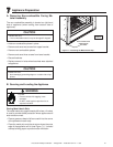
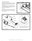
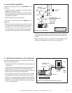
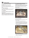
E. Junction Box Installation
If the box is being wired from the OUTSIDE of the
appliance:
• Install the Romex™ connector (not included with
appliance) in the side wrap.
• Loosen two screws on the Romex connector, feed
the necessary length of wire through the connector
and tighten the screws.
• Make all necessary wire connections.
If the box is being wired from the INSIDE of the
appliance:
• Remove the screw attaching the junction box to
the outer shell, rotate the junction box inward to
disengage it from the outer shell (see Figure 9.4).
• Pull the electrical wires from outside the appliance
through this opening into the valve compartment.
Figure 9.4 Junction Box Detail
NOTE: Do NOT wire
110 VAC to wall switch.
• Loosen the two screws on the Romex connector, feed the
necessary length of wire through the connector and tighten the
screws.
• Make all necessary wire connections to the receptacle and
assemble the receptacle and cover to the junction box.