


Special offers from our partners!

Find Replacement BBQ Parts for 20,308 Models. Repair your BBQ today.

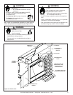
27Heat & Glo LifeStyle Collection • Twilight-II-B • 2108-900 Rev. M • 11/08
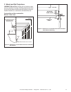
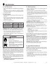
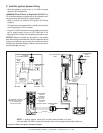
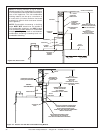
Figure 9.3 Intellifi re Pilot Ignition (IPI) Wiring Diagram
NOTE: 1. Ignition module, valve, pilot, and wall switch operate on 3 volts.
Uninterrupted 120 VAC is required at junction box unless equipped with battery back-up.
IGNITION MODULE
3 VAC
TRANSFORMER
3 VAC
GRN
ORG
INTERMITTENT
PILOT
IGNITOR
IGNITION
MODULE
(3V)
ON/OFF
WALL
SWITCH
LOW VOLTAGE
PLUG-IN
3V TRANSFORMER
NEUTRAL
HOT
GROUND
FLAME SPARKER/
SENSOR
REMOTE
CONTROL
SEE NOTE 1
ORG
WHT
VALVE
PIGGYBACK
ON/OFFSWITCH
WHITE WIRE
CAN BE
PLUGGED
INTO ANY
OF #1-#5
LOCATIONS
ON THE
NEUTRAL SIDE
BLACK WIRE CAN BE
PLUGGED INTO ANY OF
#1 - #5 LOCATIONS
ON THE HOT SIDE
BRN
BRN
VALVE
PLUG IN
GROUND TO
FIREPLACE
CHASSIS
I
S
C. Intellifi re Ignition System Wiring
• Wire the appliance junction box to 110 VAC for proper
operation of the appliance.
WARNING! Risk of Shock or Explosion! DO NOT wire
IPI controlled appliance junction box to a switched circuit.
Incorrect wiring will override IPI safety lockout.
• Refer to Figure 9.2, Intellifi re Pilot Ignition (IPI) Wiring
Diagram.
• This appliance is equipped with an Intellifi re control valve
which operates on a 3 volt system.
• Plug the 3-volt AC transformer into the appliance junction
box to supply power to the unit OR install two D cell
batteries (not included) into the battery pack before use.
NOTICE: Batteries should not be placed in the battery
pack while using the transformer. Remove batteries before
using the transformer, and unplug the transformer before
installing the batteries. Battery polarity must be correct or
module damage will occur.