


Special offers from our partners!

Find Replacement BBQ Parts for 20,308 Models. Repair your BBQ today.

Heat & Glo LifeStyle Collection • Twilight-II-B • 2108-900 Rev. M • 11/0828
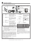
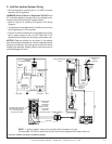
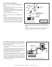
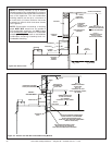
Figure 9.3 Fan Wiring Diagram
D. Optional Accessories
Optional fan and remote control kits require that 110-120
VAC be wired to the factory installed junction box before
the appliance is permanently installed (see Figure 9.3).
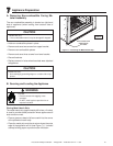
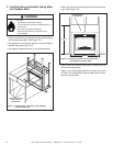
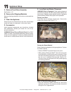
Fan Installation
To provide best airfl ow, we recommend positioning fan
on the left side (as viewed from appliance interior side
(see Figure 9.2). NOTE: It is recommended fan be in-
stalled prior to gas line installation.
Wall Switch
Position the wall switch in the desired position on a wall.
Run a maximum of 25 feet (7.8 m) or less length of 18
A.W.G. minimum wire and connect it to the appliance ON/
OFF switch pigtails.
NOTE: If any of the original wire as supplied
with the appliance must be replaced, it must be
replaced with the type 105
o
C rated wire.
Figure 9.2 Fan location
FAN
DRIP
TRAY
SEE DETAIL A
WIRE LEAD
2 FEMALE ENDS
PLUG AND WIRE
ASSEMBLY
JUNCTION BOX
6 FT.
APPROX.
TEMPERATURE
SENSOR SWITCH
FAN SPEED
CONTROL
(RHEOSTAT)
DETAIL A
WIRE LEAD
1 MALE END
1 FEMALE END
6 FT.
APPROX.
FAN KIT
#GFK-160T
APPLIANCE
INTERIOR
SIDE