Special offers from our partners!

Find Replacement BBQ Parts for 20,308 Models. Repair your BBQ today.
Part # 4526884 Rev 4 (10/08/10) Page 11
INSTALLATION continued
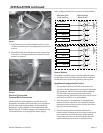
Photo F
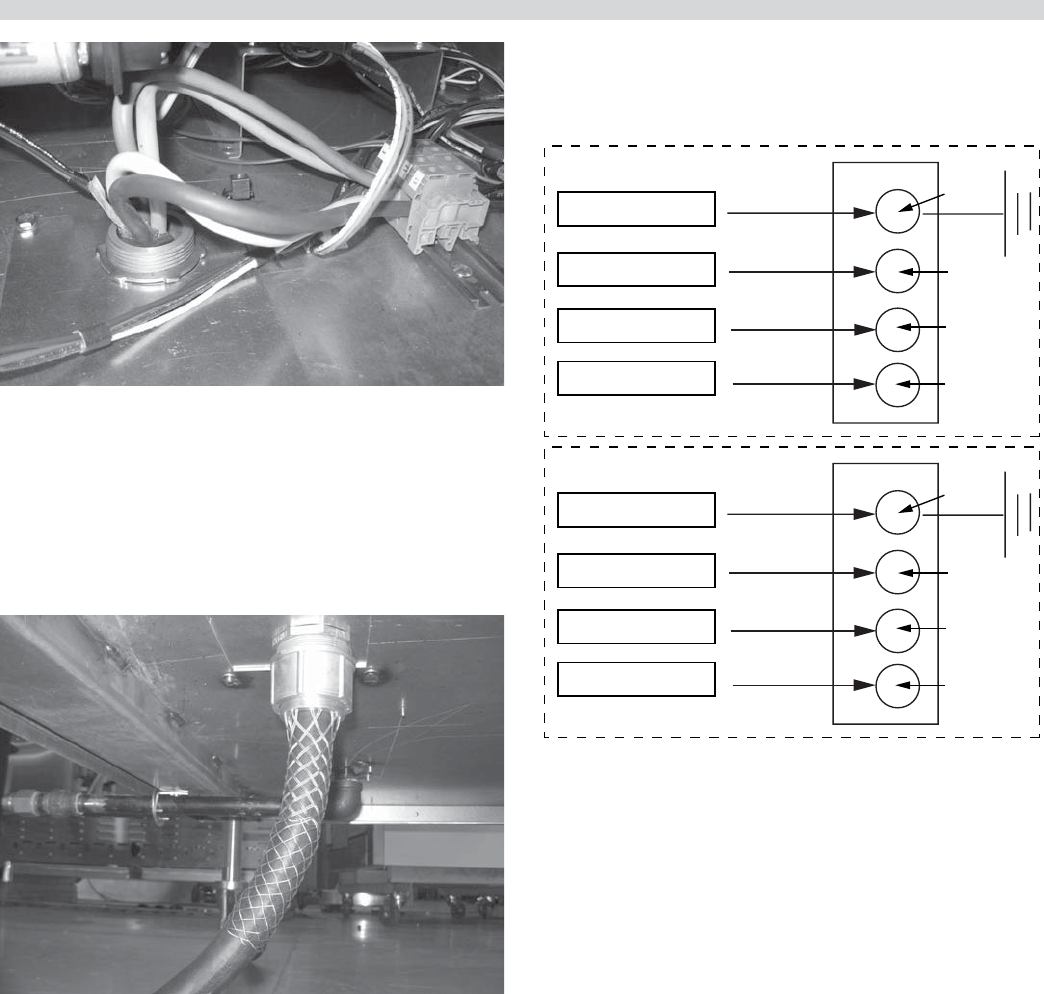
5. Attached wire ends to terminal block as shown in next
section and referenced in wiring diagrams at back of this
manual.
6. Reinstall the side panel and grease bucket support with
metal screws. The external electrical connection should
appear as in photo G.
Photo G
Electrical Connection
Terminal Block Connection
All electrically operated appliances must be electrically
grounded in accordance with local codes; or in the absence
of local codes, with the latest edition of National Wiring
Regulations. A wiring diagram is located behind the rear
panel of the grill. For proper voltages, see rating plate in the
circuit breaker box, or on the right-rear frame upright.
Note: see diagram below for connections to terminal block.
Green-Ground
White - Z
Black - Y
Red - X
Wire leads from
Cord and Plug
3-PHASE
Main Terminal
Block of Grill
G
Z
Y
X
Green-Ground
Black - Z
White - Y
Red - X
SINGLE PHASE
G
L1
N
L2
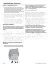
Grease Bucket:
The griddle is supplied with two stainless steel side grease
buckets that must be installed before the unit is used. Each
bucket slides into position along stainless steel supports.
Appliances Equipped with Casters:
1. The installation shall be made with a connector that
complies with the Standard for Connectors for Moveable
Gas Appliances, ANSI Z21.69 or latest edition, addenda
Z21.69a-1989, and a quick-disconnect device that
complies with the Standard for Quick Disconnects for Use
with Gas Fuel. ANSI Z21.41 or latest edition.
2. The front casters on the appliance are equipped with
brakes to limit the movement of the appliance without
placing any strain on the connector or quick-disconnect
device or its associated piping.
3. Please be aware; required restraint is attached to a
bracket (which is located on the rear caster closest to the
gas connection), and if disconnection of the restraint
is necessary; be sure to reconnect the device after the
appliance has been returned to its original position


