


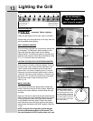
Special offers from our partners!

Find Replacement BBQ Parts for 20,308 Models. Repair your BBQ today.

Lighting the Grill
13
BEFORE LIGHTING
Important! Before Lighting...
Check the gas supply line for cuts, wear or abrasion.
Always keep your face and body as far away from the
grill as possible when lighting.
GRILL BURNER LIGHTING
This unit comes equipped with (2) electronic starters and
(6) electrodes.
The electronic igniter located on the
right shelf lights the side burner and the bottom
infrared burner. The electronic igniter on the left shelf
lights the main burners, which are controlled by knobs
2, 3, 4, 5, 6 and the back infrared burner.
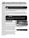
LIGHTING THE GRILL WITH ELECTRONIC IGNITERS
Always open the lid before attempting lighting. Push and
turn one of the control knobs counter clockwise to the
“HIGH” position and immediately press the electronic
igniter button. You’ll hear a snapping sound. It may be
necessary to hold the electronic igniter button for about
4 seconds. If the burner does not light in 4 seconds, turn
the knob to OFF and wait 5 minutes before trying again.
Repeat above steps to light remaining burners.
(See Fig. 16)
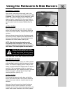
MATCH LIGHTING
If by chance the electronic igniter does not light the
burner
, the burner may be lit with a match. Attach the
match to the match extender, located inside the right
cart door.
Keep your face as far away from the grill surface as pos
-
sible and pass the match extender through the spaces
in the grill grates to the ports of the back crossover
burner
between the flavor grids. Position the match
near the burner ports, then push and turn the control
knob counter clockwise to the “HIGH” position. (See Fig.
17-18)
NOTE: If the grill will not light after several attempts
see the trouble-shooting section of this manual. T
urn
the control knobs to the OFF position when not in use.
Do not attempt to
“Light” the grill if the
odor of gas is present!!
Fig. 16
Fig. 17
Fig. 18
Crossover Burner
H
L
CONTROL KNOB LAYOUT:
The control knob bezel has
stamped markings for the HIGH
and LOW settings. Turning the
knob so the arrow faces the left
is the HIGH setting. Turning the
knob so the arrow faces down
is the LOW setting.
R
ight electronic igniter for
bottom infrared burner
(
knob #1) & side burner
(
knobs #SB1 & #SB2)
L
eft electronic igniter
for main burners #2, #3,
#
4, #5, #6 and back
i
nfrared burner
Back
I
nfrared
Knob
#
1
Knob
#
SB2
Knob
#
4
Knob
#
5
Knob
#
3
Knob
#
2
Knob
#
6
Knob
#
SB2