


Special offers from our partners!

Find Replacement BBQ Parts for 20,308 Models. Repair your BBQ today.
108862-01D
For more information, visit www.desatech.com
For more information, visit www.desatech.com
5
5
CLEARANCES
Minimum clearances to combustibles for the fireplace are as follows:
Back, and sides 0"/mm
Perpendicular walls 6" (152mm)
Floor 0"/mm
Ceiling to louver opening 42" (1067mm)
Front 36" (914mm)
Top 0"/mm
Vent (See venting instructions for
specific venting clearances.)
Combustible material with a maximum thickness of 5/8" may be
flush with the top front of fireplace .
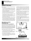
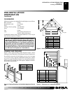
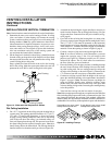
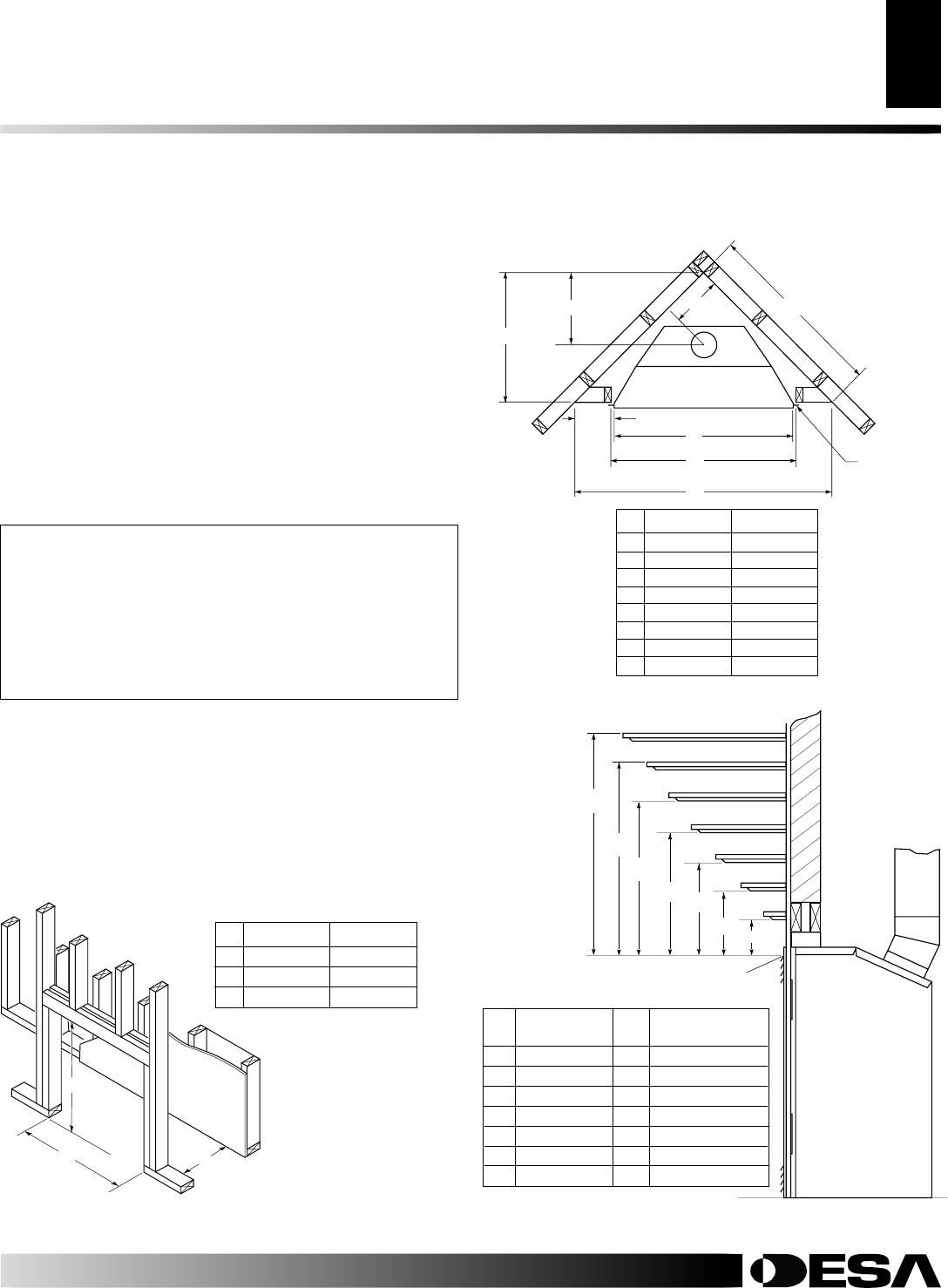
FRAMING AND FINISHING
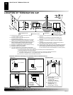
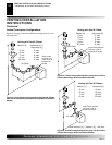
Figure 4 shows typical framing of this fireplace. Figure 5 shows
framing for corner installation. All minimum clearances must be met.
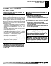
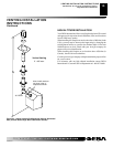
For available accessories for this fireplace, see Accessories on page
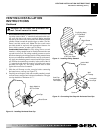
31. If you are using a separate combustible mantel piece, refer to
Figure 6 for proper installation height. You can install noncombus-
tible mantels at any height above the fireplace.
Note:
Noncombus-
tible mantels may discolor!
PRE-INSTALLATION
PREPARATION
Continued
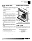
NOTICE: This fireplace is intended for use as supple-
mental heat. Use this fireplace along with your pri-
mary heating system. Do not install this fireplace as
your primary heat source. If you have a central heat-
ing system, you may run system’s circulating blower
while using fireplace. This will help circulate the heat
throughout the house. In the event of a power outage,
you can use this fireplace as a heat source.
B
C
A
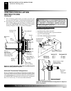
Figure 4 - Framing Clearances for Installation Against an Exterior
Wall
36" Models 42" Models
A 36
1
/8" 40
1
/8"
B 41
1
/4" 48
1
/4"
C 23
1
/2" 25
5
/8"
C
B
A
D
E
F
G
Top of Louver Opening
3
2
1
4
5
6
7
Wall
A
B
E
F
G
H
D
C
Nailing Tabs
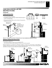
Figure 5 - Framing Clearances for Corner Installation
Ref. Mantel Depth Ref. Mantel from Top
of Louver Opening
1 14" (356mm) A 16" (406mm)
2 12" (305mm) B 14" (356mm)
3 10" (254mm) C 12" (305mm)
4 8" (203mm) D 10" (254mm)
5 6" (152mm) E 8" (203mm)
6 4" (101mm) F 6" (152mm)
7 2" (51mm) G 4" (101mm)
36" Models 42" Models
A 35
3
/4" 41
5
/8"
B 15" 21
5
/8"
C 49
5
/8" 58
1
/2"
D 10
3
/8" 13
1
/2"
E 13
3
/4" 16
3
/4"
F 41" 48"
G 41
1
/4" 48
1
/4"
H 68
1
/2" 81
1
/2"
Figure 6 - Clearances for Combustible Mantels
PRE-INSTALLATION PREPARATION
Clearances
Framing and Finishing