


Special offers from our partners!

Find Replacement BBQ Parts for 20,308 Models. Repair your BBQ today.
108862-01D
For more information, visit www.desatech.com
For more information, visit www.desatech.com
4
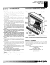
PRODUCT FEATURES
These are a few facts that can help you understand and enjoy your
direct-vent fireplace:
• The venting system may be routed to the outside of your home
in several ways. It may vent through the roof (vertical) or it may
vent to an outside/exterior wall (horizontal). The vent pipe in-
stallation is very important to allow for proper operation. You
must follow the venting instructions very carefully for either
vertical or horizontal applications.
• This fireplace may be installed in any room of your house provided
all local codes and these installation instructions are followed.
• This fireplace does not require electricity to operate.
• Only the blower requires electricity if installed and if you plan
to install the blower at a later date, do not forget to wire the
outlet at the bottom of the fireplace when framing.
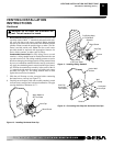
• A piezo ignitor and ceramic electrode create spark to ignite the
pilot light. It does not require any matches, batteries or any other
sources of ignition to light the pilot.
• Each time you turn on your fireplace, you may notice some
amount of condensation on the inside of the fireplace glass. This
is normal and will disappear after 10-20 minutes of operation.
• Your direct-vent gas fireplace system (fireplace and venting) is a
balanced and sealed gas operating unit. It requires approximately
10-20 minutes of operating time before the flame pattern stabilizes.
PRE-INSTALLATION
PREPARATION
LOCATION AND SPACE REQUIREMENTS
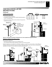
Determine the safest and most efficient location for your DESA
International direct-vent fireplace. Make sure that rafters and wall
studs are not in the way of the venting system. Choose a location
where the heat output is not affected by drafts, air conditioning
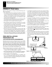
ducts, windows or doors. Figure 2 shows some common locations.
Be aware of all restrictions and precautions before deciding the
exact location for your fireplace and termination cap.
When deciding the location of your fireplace, follow these rules:
• Do not connect this fireplace venting to a chimney flue serving
a separate solid-fuel burning fireplace or appliance.
• Due to high temperatures, do not locate this fireplace in high traf-
fic areas, windy or drafty areas, or near furniture or draperies.
• Proper clearances must be maintained.
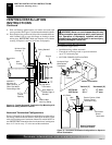
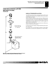
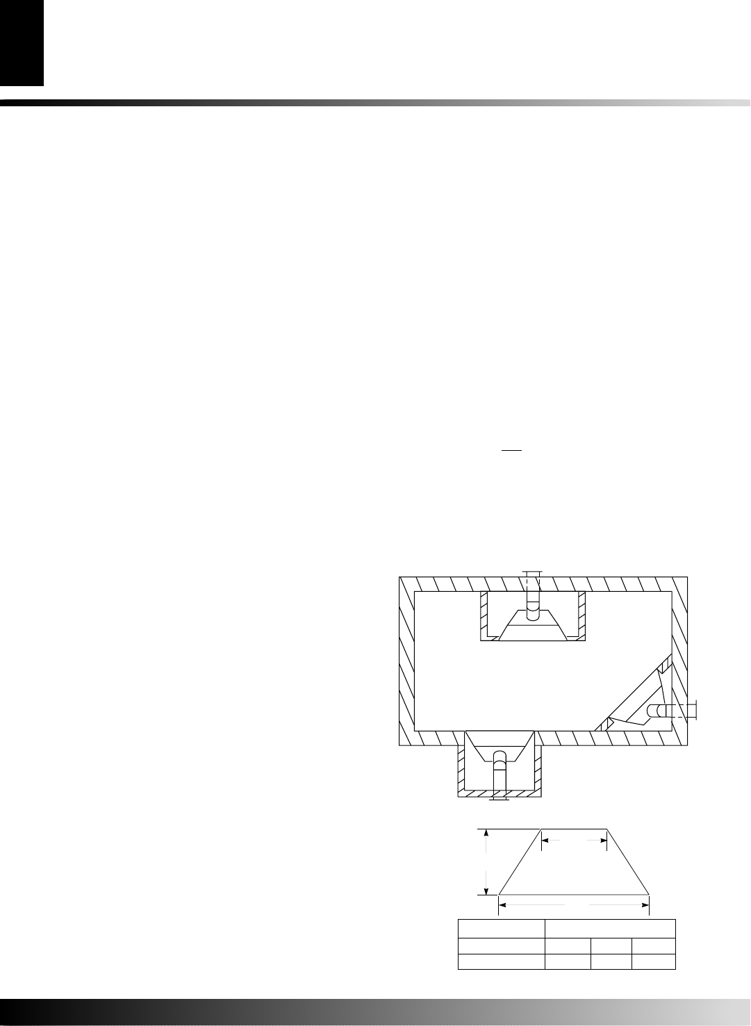
• If your fireplace is to be installed directly on carpeting, vinyl
tile, or any combustible material other than wood, it must be
installed on a metal or wood panel extending the full width and
depth of the fireplace. See Figure 3.
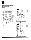
• Your fireplace is designed to be used in zero clearance installa-
tions. Wall or framing material can be placed directly against
any exterior surface on the back, sides, or top of your fireplace,
except where standoff spacers are integrally attached. If stand-
off spacers are attached to your fireplace, these spacers can be
placed directly against wall or framing material. See framing
details on page 5.
• If you plan on installing a television or entertainment center re-
cessed above your fireplace, it is recommended that you main-
tain a minimum 18" above top of louver opening.
• When locating termination cap, it is important to observe the
minimum clearances shown in Figure 7, page 6.
• If recessing into a wall, you can avoid extra framing by position-
ing your fireplace against an already existing framing member.
• Do not recess termination cap into a wall or siding.
• You may paint the termination cap with 450ºF (232ºC) heat-
resistant paint to coordinate with the exterior finish.
• There must not be any obstruction such as bushes, garden sheds,
fences, decks, or utility buildings within 24" from the front of
the termination cap.
• Do not locate termination cap where excessive snow or ice build
up may occur. Be sure to clear vent termination area after snow
falls to prevent accidental blockage of venting system. When
using snow blowers, do not direct snow towards vent termina-
tion area.
PRODUCT FEATURES
PRE-INSTALLATION PREPARATION
Location and Space Requirements
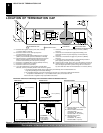
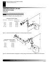
Fireplace size D x FW x RW
36" 21
1
/8" 41" 29"
42" 23
1
/4" 48" 36
1
/4"
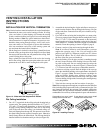
Figure 2 - Common Fireplace Locations
Flush with a wall
Through exterior wall
enclosed in a chase
Corner
installation
Figure 3 - Fireplace Bottom Dimensions
D
RW
FW