


Special offers from our partners!

Find Replacement BBQ Parts for 20,308 Models. Repair your BBQ today.
108862-01D
For more information, visit www.desatech.com
For more information, visit www.desatech.com
24
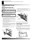
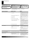
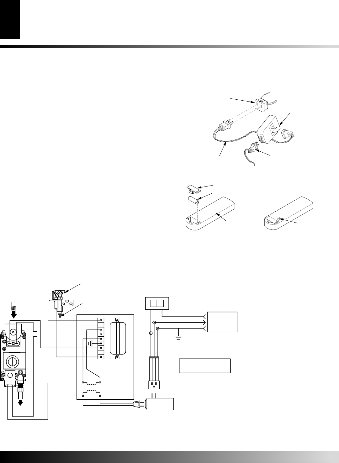
OPTIONAL REMOTE CONTROL
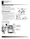
INSTALLATION (Model WRC)
Note:
If using optional wireless hand-held remote control, the wall
switch must be in the ON position to be operational. The remote control
then becomes the switching mechanism for fireplace operation.
1. Open lower louver panel.
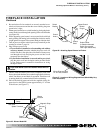
2. The WRC model receiver does not require a battery. The re-
ceiver can be installed by first plugging the short extension
cord into the fireplace receptacle. Then plug the receiver unit
into the extension cord. Finally plug the ignition module plug
into the receiver unit (see Figure 47).
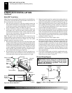
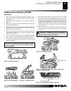
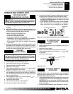
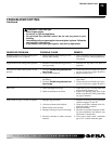
3. Activate the remote handset battery by removing the insulat-
ing tab on the back of the handset (see Figure 48). The battery
is included pre-installed.
4. Once the battery is activated the unit is ready to use.
5. Close lower louver panel.
Figure 47 - Installing the WRC Remote Receiver
Fireplace
Receptacle
Remote Control
Receiver
Extension Cord
Ignition
Module Plug
Figure 48 - Installing Battery into Back of Handset
Pull to Remove
Insulation Tab
Battery Cover
12 Volt Battery
Back of
Handset
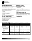
Robertshaw
MODEL SP745 IGNITION CONTROL
STEP DOWN
TRANSFORMER
PV
GND
PV/MV
TR
MV
TH
IGN
EV2
INCOMING MAIN
GAS SUPPLY
EV1
GAS LINE TO
BURNER
24V AC
120V AC
INCOMING
120V AC
(FUSE BOX
OR BREAKER)
OFF
ON
(SUPPLIED)
WALL SWITCH
GREEN
BLACK
WHITE
120v, 60Hz, 0.7A
ELECTRICAL RATING:
BLACK
WHITE
GREEN
OPTIONAL
REMOTE
CONTROL
WIRING DIAGRAM
Pilot
Burner
Pilot Gas
Line
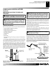
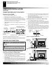
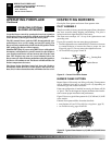
WALL SWITCH INSTALLATION
The installation of a wall switch allows you to activate the gas
control valve and turn the fireplace on and off. The wall switch is
to be connected to the incoming 120 volt regular household wiring
that supplies the electricity to the fireplace. Refer to wiring
diagram below.
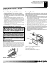
FIREPLACE INSTALLATION
Wall Switch Installation
Optional Remote Control Installation
WIRING DIAGRAM
FIREPLACE INSTALLATION
Continued