


Special offers from our partners!

Find Replacement BBQ Parts for 20,308 Models. Repair your BBQ today.

108660-01D
8
For more information, visit www.desatech.com
For more information, visit www.desatech.com
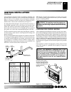
VENTING INSTALLATION
A B-type venting system must be connected to the appliance for
venting to the outside of the building.
The following section is provided as a guide to a standard B-type
vent installation.
Standing codes requirements concerning B-type vent installations
may vary within your state, province or local codes jurisdiction.
Therefore, it is recommended that you check with your local
building codes for specific requirements or in absence of local
codes, follow Section 7.0 of the current National Fuel Gas Code
NFPA No. 54/ANSI Z223.1 and in Canada with CAN/CSA B149 for
Category I systems using double wall B-1 vent pipe .
This gas appliance must be vented to the outdoors only and may not
be terminated into an attic space or into a chimney flue servicing a
solid-fuel burning appliance.
This appliance may be vented through a manufactured chimney
system or a masonry chimney using a B-vent adapter or a chimney
liner system if all are listed, inspected and approved by local codes
and/or building authorities.
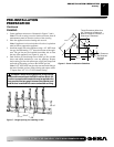
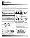
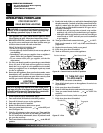
The examples shown in Figure 10 are typical of most B-vent
installations and codes practices.
Example 1:
Shows the minimum allowable system height and
lateral offset for a 60° degree or greater inclination. Code specifies
that offsets at 60° degrees or greater are considered horizontal and
must follow the 75% percent rule for lateral to total vertical system
height. Codes also allows only one offset in the total system when
at 60° degrees or greater. The total vertical height in this example
represents the minimum height of 8 feet and therefore the allowable
lateral is 6 feet when the 75% percent rule applies. If the lateral
length must exceed 75% then the system must be sized in accor-
dance with the Category I venting tables.
Example 2:
Shows a multiple offset each at 45° degrees of
inclination. Multiple offsets are permitted if they do not exceed 45°
degrees of inclination. The total lengths of the two offsets are not
required to meet the 75% percent allowable rule.
Example 3:
Shows a single offset at 45° degrees of inclination and
therefore the lateral length at 10 feet of offset does not have to meet
the 75% percent rule.
In each case the offsets must be supported and firestops must be
positioned wherever the vent must pass through a sub-floor, ceiling
joist or an attic overhang. The vent pipe must terminate vertically
into a listed type vent cap and extend a sufficient height through an
approved roof flashing, roof jack or a roof thimble. At all points the
listed clearances must be maintained.
Maintain
Listed
Clearance
12' Min.
12' Min.
45°
45°
6'
8'
12' Min.
60°
45°
Position
Firestop
Position
Firestop
Position
Firestop
Listed
Vent Cap
Listed
Vent Cap
Listed
Vent Cap
Maintain
Listed
Clearance
Maintain
Listed
Clearance
Maintain
Listed
Clearance
Maintain
Listed
Clearance
Maintain
Listed
Clearance
Support Each
Lateral At
Least Every
Six (6) Feet
Maintain
Listed
Clearance
10'
EXAMPLE 3EXAMPLE 2EXAMPLE 1
Figure 9 - Typical B-Vent Configuration
VENTING INSTALLATION