


Special offers from our partners!

Find Replacement BBQ Parts for 20,308 Models. Repair your BBQ today.
108660-01D
11
11
For more information, visit www.desatech.com
For more information, visit www.desatech.com
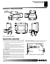
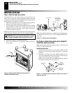
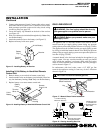
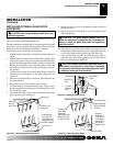
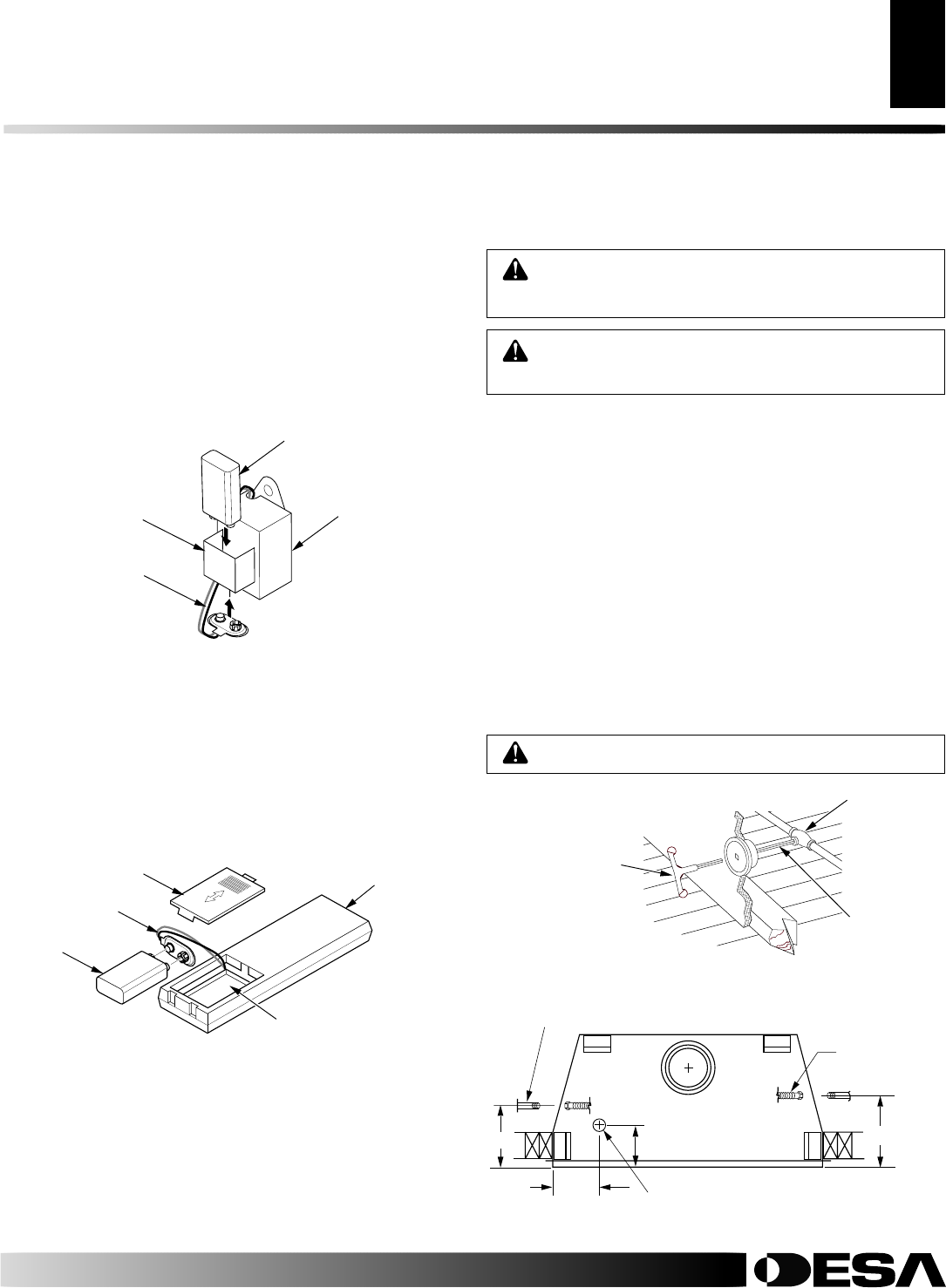
Installing 9-Volt Battery in Hand-Held Remote
Control Unit
1. Remove battery cover on back of remote control unit.
2. Attach terminal wires to the battery (not included). Place bat-
tery into the battery housing.
Note:
Only use alkaline battery.
3. Replace battery cover onto remote control unit.
Figure 16 - Installing Battery in Hand-Held Remote Control Unit
Battery
Cover
9-Volt
Battery
Terminal
Wires
Remote
Control Unit
Battery
Housing
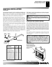
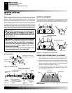
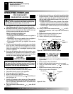
Figure 15 - Installing Battery in Receiver
Battery
Clip
9-Volt Battery
Receiver
Terminal
Wires
INSTALLATION
Continued
4. Connect wires to control circuit. Connect white wire to termi-
nal marked TH/TP on control valve. Connect red wire to male
blade connector provided at open end of safety circuit wiring
(see Wiring Diagram, page 29).
5. Locate the battery clip mounted on the back of the receiver
(see Figure 15).
6. Slide 9-volt battery (not included) through the clip.
Note:
Only
use alkaline battery.
7. Attach the terminal wires to the battery (see Figure 15).
8. Replace refractory brick access panel.
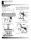
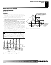
GAS LINE HOOK-UP
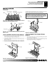
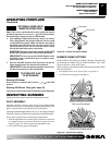
Figure 17 - Manual Shutoff Valve Installation
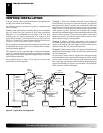
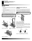
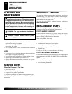
Figure 18 - Routing Incoming Gas Line
WARNING: Gas line hookup should be done by
your gas supplier or a qualified service person.
WARNING: Before you proceed, make sure your
gas supply is OFF.
Typical Exterior Wall Gas
Shutoff Installation
CAUTION: Do not kink flexible gas line.
The appliance and it’s individual shutoff valve must be discon-
nected from the gas supply piping system during any pressure
testing of that system at test pressures in excess of 1/2 psig (3.5 kPa).
The appliance must be isolated from the gas supply piping system
by closing its individual manual shutoff valve during any pressure
testing of the gas supply piping system at test pressures equal to or
less than 1/2 psig (3.5 kPa).
A manual shutoff valve has been included in the appliance’s gas
supply system. You may consider installing an extra gas shutoff
valve outside the appliance’s enclosure (check with local codes)
where it can be accessed more conveniently with a key through a
wall as shown in Figure 17.
In conformance with local codes, route a 1/2" NPT gas line
towards the appliance coming in from any of the 3 directions
shown in Figure 18.
Key
Extension
Shutoff
Valve
8
3
/
8
"
10
5
/
8
"
1/2" NPT Incoming
Black Iron Gas Line
Flexible Gas Line
(1 Provided) Can
Be Extended Out
Either Side
7"
7"
Alternate Gas Supply
Through Sub-Floor
INSTALLATION
Optional Wireless Hand-Held Remote Control Installation (Cont.)
Gas Line Hook-Up