


Special offers from our partners!

Find Replacement BBQ Parts for 20,308 Models. Repair your BBQ today.
108660-01D
10
For more information, visit www.desatech.com
For more information, visit www.desatech.com
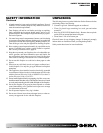
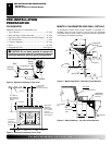
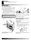
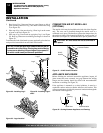
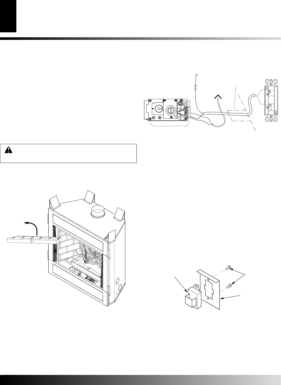
Figure 13 - Wall Switch Wiring Diagram
Note:
If any of the original wire as supplied must be replaced, use
18 AWG TYPE CL2 (UL) 105 C (25 ft. length MAXIMUM) or
equivalent.
OPTIONAL WIRELESS HAND-HELD REMOTE
CONTROL INSTALLATION
Note:
If using optional wireless hand-held remote control, the wall
switch is no longer operational.
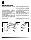
Installing Receiver
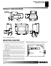
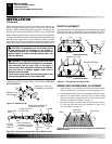
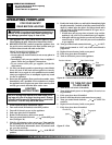
1. Remove the front refractory access panel by lifting up and
angling out of the firebox opening (see Figure 12) to expose
controls.
2. Disconnect wall switch wires from TH/TP terminals on con-
trol valve and the blade connector on safety circuit wiring (see
Figure 13 and Wiring Diagram on page 29).
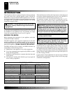
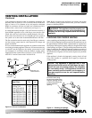
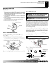
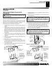
3. Install remote receiver unit onto mounting bracket using the
two plastic mounting clips (see Figure 14).
Figure 14 - Installing Remote Receiver (Shown from Rear of
Mounting Bracket)
INSTALLATION
WARNING: Do not wire remote wall switch to main
power supply (Standard 120v household current).
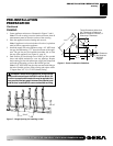
WALL SWITCH INSTALLATION
The installation of a wall switch allows you to activate the gas
control valve without the normal household electricity since the
valve operates on millivolt current supplied by the heat generated by
the thermopile. To install the wall switch:
1. Remove the front refractory access panel by lifting up and an-
gling out of the firebox opening (see Figure 13).
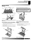
2. Use wire and connectors provided. Attach red wire to terminal
marked TH/TP on control valve. Attach white wire to blade
connector on open end of safety circuit wiring (see Figure 13
and Wiring Diagram, page 29).
Note:
If any of the original wire from the unit control must be replaced,
use the same type or a higher rated wire (25 ft. maximum length).
Receiver
Mounting
Bracket
Plastic
Mounting
Clips
Figure 12 - Removing Front Refractory Access Panel
(P325B/VP325 Model Shown)
4. Locate wall switch in a convenient location.
5. After wire connections are complete, replace refractory
access panel.
INSTALLATION
Wall Switch Installation
Optional Wireless Hand-Held Remote Control Installation
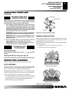
Conduit Sleeve
To Safety Circuit
Route Millivolt
Through Gas Line
To Thermopile
Wires (Supplied)
Wall Switch
(Back View)
IN
T
H
T
P
T
H
T
P
I
N
O
U
T
O
F
F
P
I
L
O
T
O
N