


Special offers from our partners!

Find Replacement BBQ Parts for 20,308 Models. Repair your BBQ today.
111921-01D
For more information, visit www.desatech.com
For more information, visit www.desatech.com
21
21
FIREPLACE INSTALLATION
Continued
FIREPLACE INSTALLATION
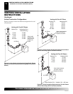
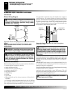
Installing Optional Wireless Hand-Held Remote Control - GHRCB and GHRCTB Series
Removing/Replacing Glass Door
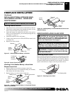
Installing 9-Volt Alkaline Battery in Hand-Held
Remote Control Unit
1. Remove battery cover on back of remote control unit.
2. Attach terminal wires to a 9-volt alkaline battery (not included).
Place battery into the battery housing.
3. Replace battery cover onto remote control unit.
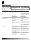
Figure 39 - Installing Alkaline Battery in Hand-Held Remote
Control Unit (GHRCB)
Battery Cover
9-Volt
Alkaline
Battery
Terminal
Wires
Remote Control Unit
Battery
Housing
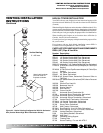
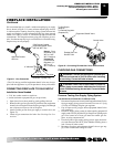
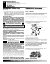
Figure 40 - Installing Battery in Hand-Held Remote Control Unit
(GHRCTB Series)
Remote
Control
Unit
Battery
Cover
9-Volt
Battery
Terminal
Wires
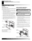
REMOVING/REPLACING GLASS DOOR
CAUTION: Do not operate this fireplace with a
broken glass door panel or without the glass door
panel securely in place. For replacement part infor-
mation see
Replacement Parts
, page 31.
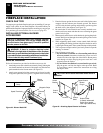
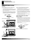
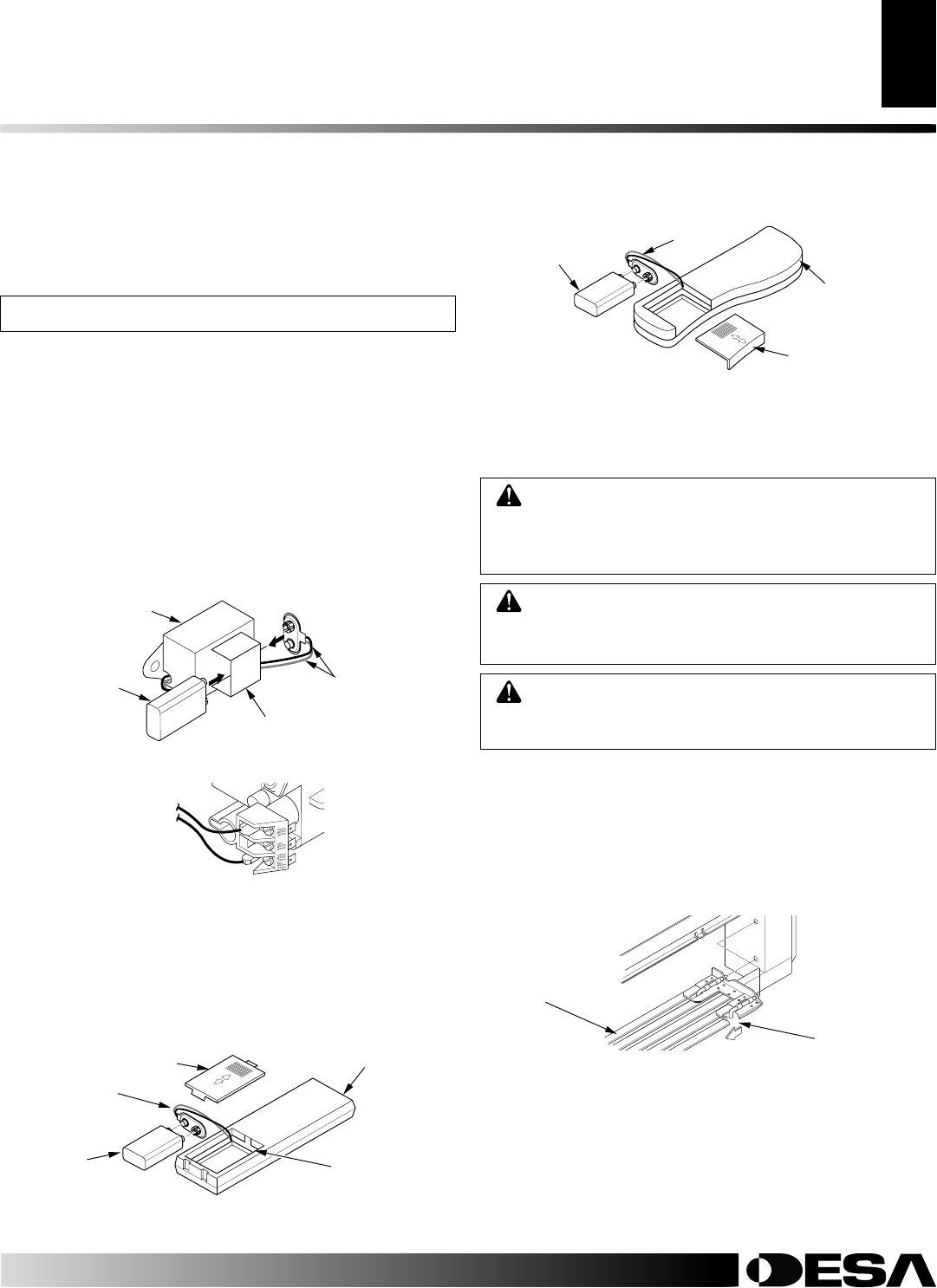
Removing Louver Panels
Remove the top and bottom louver panels by simultaneously pulling
both top end spring latches towards the center of the appliance until
they are disengaged from the locating holes (see Figure 41). Repeat
for bottom spring latches and pull the louvers outward. To install or
replace items removed, simply reverse the procedures above.
Figure 41 - Removing Louver Panel
Louver Panel
CAUTION: Wear gloves and safety glasses while
handling or removing broken glass. Do not remove if
glass is hot. Keep children and pets away from glass.
WARNING: If fireplace has been running, turn
off and unplug fireplace. Let cool before removing
glass door or louvers.
Spring Latch
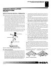
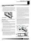
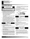
Installing Remote Receiver
1. Open bottom louver and locate the switch bracket on the left.
2. Unscrew the switch bracket. Lean bracket forward so you are
able to access the back of the remote receiver.
3. Locate the battery clip mounted on the back of the receiver.
Slide a 9-volt alkaline battery (not included) through the clip
(see Figure 37, page 21).
4. Attach the terminal wires to the battery.
5. Connect wires from receiver to TH and TPTH to control valve
(see Figure 38).
6. Replace the switch bracket.
INSTALLING OPTIONAL WIRELESS HAND-
HELD REMOTE CONTROL - GHRCB AND
GHRCTB SERIES
NOTICE: Use only alkaline batteries (not included).
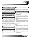
Figure 37 - Attaching Alkaline Battery to Receiver
Figure 38 - Control Valve Terminals
To Optional
Remote
Accessory
9-Volt
Alkaline
Battery
Receiver
Terminal
Wires
Battery Clip