


Special offers from our partners!

Find Replacement BBQ Parts for 20,308 Models. Repair your BBQ today.
111923-01A
For more information, visit www.desatech.com
For more information, visit www.desatech.com
19
19
FIREPLACE INSTALLATION
Continued
FIREPLACE INSTALLATION
Installing Gas Piping to Fireplace Location (Cont.)
Connecting Fireplace to Gas Supply
Checking Gas Connections
Installation must include an equipment shutoff valve, union, and
plugged 1/8" NPT tap. Locate NPT tap within reach for test gauge
hook up. NPT tap must be upstream from fireplace (see Figure 31).
IMPORTANT:
Install main gas valve (equipment shutoff valve) in
an accessible location. The main gas valve is for turning on or
shutting off the gas to the appliance.
Check your building codes for any special requirements for locating
equipment shutoff valve to fireplaces.
Apply pipe joint sealant lightly to male NPT threads. This will
prevent excess sealant from going into pipe. Excess sealant in pipe
could result in clogged fireplace valves.
CAUTION: Use only new, black iron or steel pipe.
Internally-tinned copper tubing may be used in certain
areas. Check your local codes. Use pipe of 1/2" diam-
eter or greater to allow proper gas volume to fireplace.
If pipe is too small, undue loss of volume will occur.
WARNING: Use pipe joint sealant that is resistant
to liquid petroleum (LP) gas.
We recommend that you install a sediment trap/drip leg in supply
line as shown in Figure 31. Locate sediment trap/drip leg where it
is within reach for cleaning. Install in piping system between fuel
supply and fireplace. Locate sediment trap/drip leg where trapped
matter is not likely to freeze. A sediment trap traps moisture and
contaminants. This keeps them from going into fireplace gas con-
trols. If sediment trap/drip leg is not installed or is installed wrong,
fireplace may not run properly.
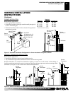
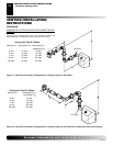
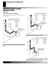
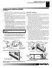
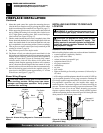
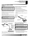
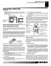
Figure 31 - Gas Connection
CSA Design-Certified
Equipment Shutoff Valve
with 1/8" NPT Tap*
3" Minimum
Approved Flexible
Gas Line
Cap Pipe Nipple Tee Joint
Sediment Trap/Drip Leg
Natural - From
Gas Meter (5.5"
W.C. to 10.5"
W.C. Pressure)
Propane/LP
From External
Regulator (11"
W.C. to 14"
W.C. Pressure)
* The CSA design-certified equipment shutoff valve may be sup-
plied with the appliance or you can purchase it from your retailer.
Pressure Testing Gas Supply Piping System
Test Pressures In Excess Of 1/2 PSIG (3.5 kPa)
1. Disconnect fireplace and its individual equipment shutoff valve
from gas supply piping system. Pressures in excess of 1/2 psig
(3.5 kPa) will damage fireplace gas regulator.
CHECKING GAS CONNECTIONS
WARNING: Test all gas piping and connections ,
internal and external to unit, for leaks after installing
or servicing. Correct all leaks at once.
WARNING: Never use an open flame to check for a
leak. Apply noncorrosive leak detection fluid to all joints.
Bubbles forming show a leak. Correct all leaks at once.
CONNECTING FIREPLACE TO GAS SUPPLY
Installation Items Needed
• 5/16" hex socket wrench or nut-driver
• sealant (resistant to propane/LP gas, not provided)
1. Open lower louver door panel by gently pulling forward.
2. Route flexible gas line (provided by installer) from equipment
shutoff valve to fireplace. Route flexible gas supply line through
one of the access holes on side of fireplace.
3. Attach flexible gas line from gas supply to control valve (see
Figure 32).
4. Check all gas connections for leaks. See Checking Gas
Connections.
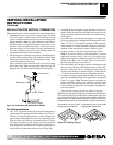
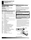
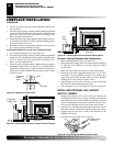
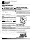
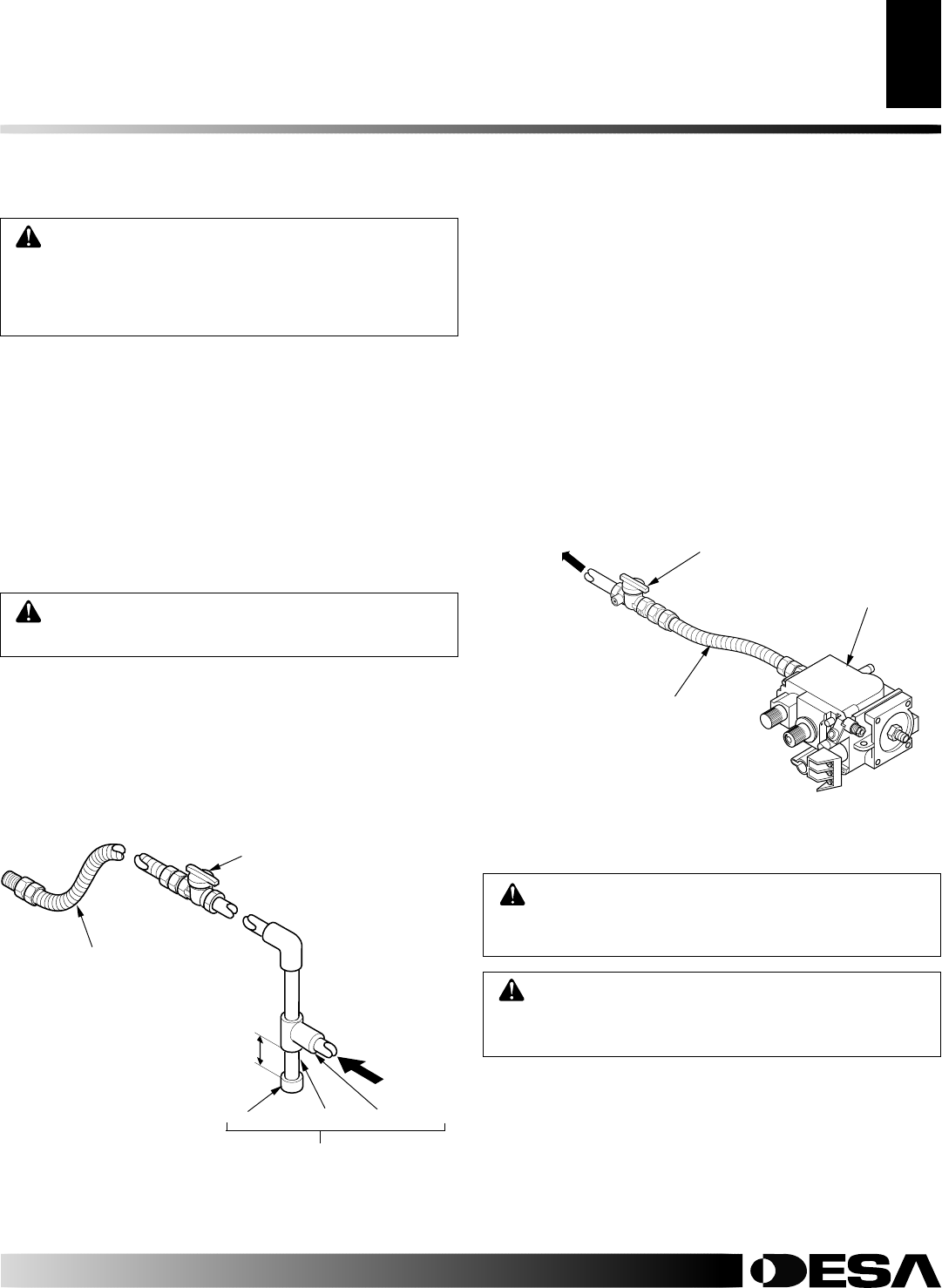
Figure 32 - Connecting Flexible Gas Line to Millivolt Valve
Flexible Gas Line
Do NOT Kink
Equipment
Shutoff Valve
To Gas Supply
(Natural)
To External
Regulator
(Propane/LP)
Control Valve