


Special offers from our partners!

Find Replacement BBQ Parts for 20,308 Models. Repair your BBQ today.
111923-01A
For more information, visit www.desatech.com
For more information, visit www.desatech.com
16
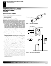
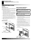
CHECK GAS TYPE
Use proper gas type for the fireplace unit you are installing. If you have
conflicting gas types, do not install fireplace. See retailer where you
purchased the fireplace for proper fireplace according to your gas type
or to purchase gas conversion kit (see Accessories, page 36).
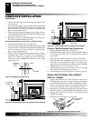
INSTALLING OPTIONAL BLOWER
ACCESSORIES
NOTICE: If installing blower in an existing fireplace
with gas connections, shut off gas supply and dis-
connect heater from gas supply. Contact a qualified
service person to do this.
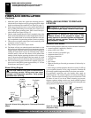
WARNING: If there is a duplex electrical outlet
installed in the right side of the bottom of the fireplace
base area, be sure that the electrical power to the outlet
is turned off before proceeding with blower installation.
Failure to do this may result in serious injury.
.
FIREPLACE INSTALLATION
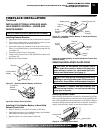
Model BK Installation
Follow all instructions provided in the blower accessory kit.
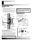
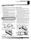
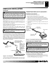
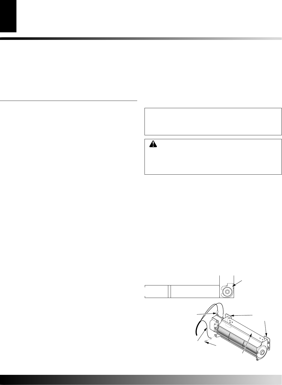
1. Attach the power cord to the blower motor by firmly pushing the
two female terminals at the end of the power cord onto the two
spade terminals on the blower motor (see Figure 25).
2. Attach green ground wire from power cord to blower housing
using screw provided (see Figure 25). Tighten screws securely.
3. Place the blower against the lower rear wall of the firebox outer
wrapper with the exhaust port directed upward. The blower
will fit inside the back opening and be held in position against
the back wall by the magnets (see Figure 25).
4. Be certain that all wire terminals are securely attached to ter-
minals on blower motor and that the screw retaining the green
ground wire is tight.
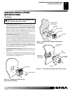
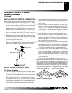
Figure 25 - Blower Model BK
Magnetic
Strips
Exhaust Port
Screw
Green Ground Wire
Spade Terminals
Side View
Lower Firebox
Cavity
Blower
Location
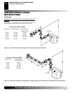
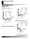
PARTS LISTS FOR VENTING KITS AND
COMPONENTS
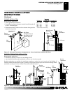
DESA (5/8") Pipe & Vent Kits
Number Description
P58-6 6" Section Double Wall Pipe, Galvanized
P58-12 12" Section Double Wall Pipe, Galvanized
P58-24 24" Section Double Wall Pipe, Galvanized
P58-36 36" Section Double Wall Pipe, Galvanized
P58-48 48" Section Double Wall Pipe, Galvanized
PA58-712 Adjustable 7"-12" Section Double Wall Pipe, Galva-
nized
FPA58-6 6" Duravent Collar to FMI Pipe Adaptor (6" Collar/Pipe
Section)
DPA58-6 6" FMI Collar to Pipe Duravent Adaptor (6" Collar/Pipe
Section)
E58-45 45° Elbow, Galvanized
E58-90 90° Elbow, Galvanized
FSE58-45 45° Starter Elbow, Galvanized (Duravent Collar to
FMI Pipe)
DSE58-45 45 deg. Starter Elbow, Galvanized (FMI Collar to
Duravent Pipe)
VKG-58 Ground Floor Vent Kit
VKB-58 Basement Vent Kit
VKS-58 Snorkel Vent Kit
VKR-58 Roof Vent Kit
VKC-58 Corner Vent Kit
HTK Horizontal Round Termination Kit
HT-58 Horizontal Round Termination, Galvanized
HTS-58 Horizontal Square Termination, Galvanized
VT-58 Vertical Round Termination, Galvanized
ST-58-14 14" Snorkel Termination, Galvanized
ST-58-36 36" Snorkel Termination, Galvanized
SC-58 Storm Collar, Galvanized
WF-58 Wall Firestop, Galvanized
RF-58-6 Roof Flashing - 0 to 6/12 Pitch, Galvanized
RF-58-12 Roof Flashing - 6/12 to 12/12 Pitch, Galvanized
VR-58 Vertical Restrictor, Galvanized
S-58 Vinyl Siding Standoff, Galvanized
WS-58 Wall Strap
CS-58 Cathedral Ceiling Support
FP-58 Firestop Plate
SF-58 Stucco Flashing - For use with HTS-5
VENTING INSTALLATION
INSTRUCTIONS
Continued
VENTING INSTALLATION INSTRUCTIONS
Parts Lists for Venting Kits and Components
FIREPLACE INSTALLATION
Check Gas Type
Installing Optional Blower Accessories