


Special offers from our partners!

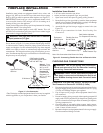
Find Replacement BBQ Parts for 20,308 Models. Repair your BBQ today.
www.desatech.com
111924-01D20
FIREPLACE INSTALLATION
Continued
GLOWING EMBERS
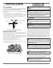
Each log is marked with a number. These numbers will help you
identify the log when installing. It is very important to install these
logs exactly as instructed. Do not modify logs. Only use logs sup-
plied with replace.
Open louvers, remove screen, unlock door latches, and open glass
door. See steps 1 and 2 of Removing/Replacing Glass Door, page 19.
Install logs according to instructions for replace model numbers.
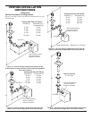
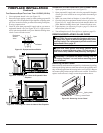
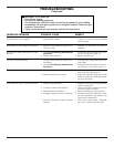
1. Place log #1 (left base log) onto pin on left side of burner as
shown in Figure 39.
2. Place log #2 (right base log) onto pin on right side of burner
as shown in Figure 39.
3. Place logs #3 (left front log) and log #4 (right front log) onto
pins as shown in Figure 40.
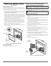
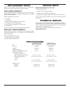
4. Place log #5 (right rear log) onto pins on right rear of burner
(see Figure 41). Rest log #6 (middle crossover log) on top of
log number 2 as shown in Figure 41.
5. Place back end of log #7 (left rear log) onto pin on left rear
burner and rest front onto log #1 as shown in Figure 42.
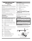
6. Rest log #8 (left crossover log) onto log #3 and rest log #9 (right
crossover log) onto logs #4 and #5 as shown in Figure 43.
Figure 39 - Installing Logs
No. 1 and No. 2
1
2
3
4
5
6
7
Figure 40 - Installing Logs
No. 3 and No. 4
Figure 41 - Installing Logs
No. 5 and No. 6
Figure 42 - Installing Log
No. 7
8
9
Figure 43 - Installing Logs No. 8 and No. 9
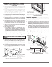
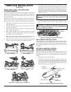
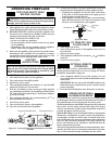
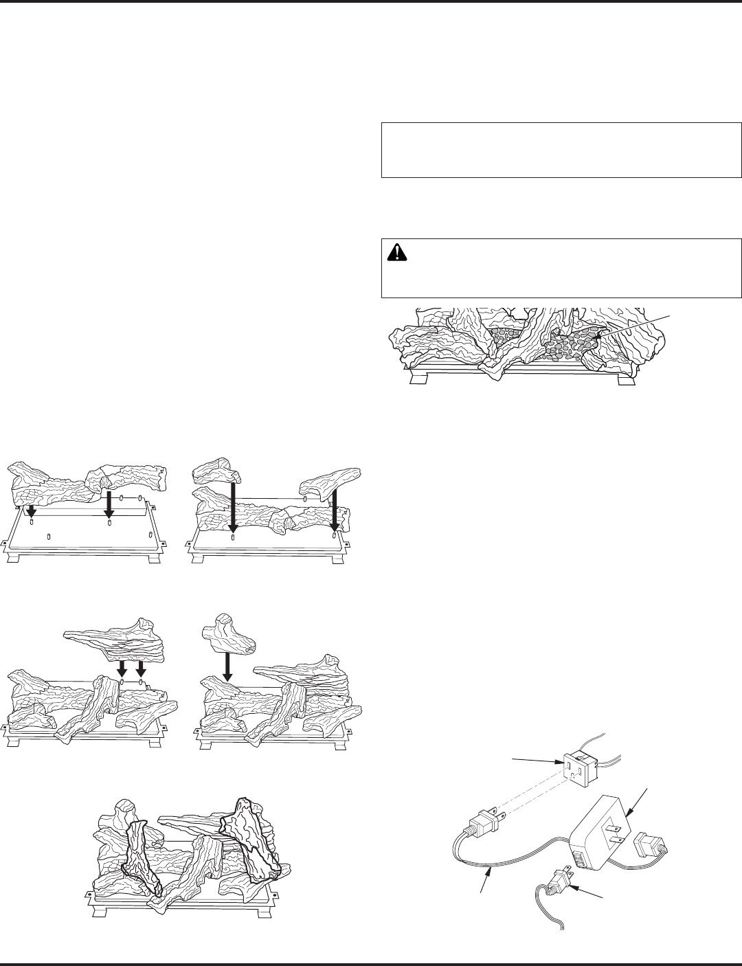
7. Pull ember material apart into pieces no larger than a dime.
Place these pieces loosely and sparingly directly onto the
exposed front section of the burner (see Figure 44). This will
create the glowing ember appearance as the ame touches the
ember material. Do not block air slots by using too much ember
material in one area. It is not necessary to use all of the ember
material provided.
problems.
8. Close glass door, lock door latches, replace screen, and close
louvers (see Removing Glass Door, steps 5 through 7, page
19).
WARNING: The glass door must be securely in place
Figure 44 - Placing Ember Material on Burner
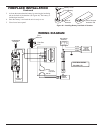
The installation of a wall switch allows you to activate the gas
control valve and turn the replace on and off. The wall switch is
to be connected to the incoming 120 volt regular household wiring
that supplies the electricity to the replace. See Wiring Diagram
on page 21.
Note: If using optional wireless hand-held remote control, the wall
switch must be in the ON position to be operational. The remote
control then becomes the switching mechanism for replace op-
eration.
1. Open lower louver panel of rebox.
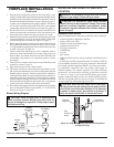
2. The WRC model receiver does not require a battery. The
receiver can be installed by rst plugging the short extension
cord into the replace receptacle. Then plug the receiver unit
into the extension cord. Finally plug the ignition module plug
into the receiver unit (see Figure 45).
Figure 45 - Installing the WRC Remote Receiver
Fireplace
Receptacle
Remote Control
Receiver
Extension Cord
Ignition
Module Plug
Ember
Material