


Special offers from our partners!

Find Replacement BBQ Parts for 20,308 Models. Repair your BBQ today.
12
105648
UNVENTED PROPANE/LP GAS FIREPLACE INSERT
DESA INTERNATIONAL
For more information, visit www.desatech.com
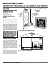
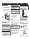
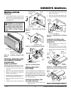
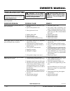
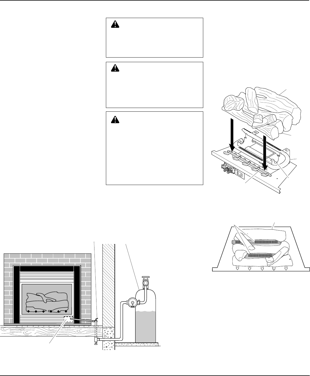
Figure 23 - Installing One Piece Log Set
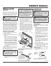
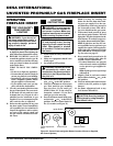
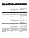
Figure 24 - Installing One Piece Log Set
(Top View)
WARNING: After installation
and periodically thereafter, check
to ensure that no flame comes in
contact with any log. With the
heater set to High, check to see if
flames contact any log. If so, re-
position logs according to the
log installation instructions in this
manual. Flames contacting logs
will create soot.
WARNING: Failure to position
the parts in accordance with these
diagrams or failure to use only
parts specifically approved with
this heater may result in property
damage or personal injury.
INSTALLING LOGS
It is very important to install the logs exactly
as instructed. Do not modify logs. Only use
logs supplied with heater.
1. Place one-piece log set on grate to fit
as illustrated in Figure 23. Make sure
middle section at bottom of log set is
seated into "U"-shaped cutout in cen-
ter of chassis (see Figure 24).
IMPORTANT:
Make sure log does not
cover any burner ports.
CAUTION: Do not remove the
warning and instruction labels
attached to the heater base as-
sembly. These markings contain
important warranty information.
INSTALLATION
Continued
One Piece Log Set
Burner Ports
O
F
F
P
I
L
O
T
O
N
H
I
L
O
Chassis
"U"-shaped
Cutout in
Chassis
One Piece
Log Set
Burner
Middle
Section at
Bottom of
Log Set
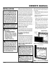
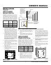
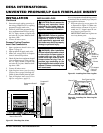
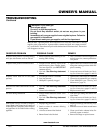
Figure 22 - Checking Gas Joints
2. Pressurize supply piping system by ei-
ther using compressed air or opening
propane/LP supply tank valve.
3. Check all joints from propane/LP sup-
ply to equipment shutoff valve (see Fig-
ure 22). Apply mixture of liquid soap
and water to gas joints. Bubbles form-
ing show a leak.
4. Correct all leaks at once.
Pressure Testing Fireplace
Insert Gas Connections
1. Open equipment shutoff valve (see
Figure 21, page 11).
2. Open propane/LP supply tank valve.
3. Make sure control knob of fireplace
insert is in the OFF position.
4. Check all joints from equipment shutoff
valve to thermostat gas valve (see Fig-
ure 22). Apply mixture of liquid soap
and water to gas joints. Bubbles form-
ing show a leak.
5. Correct all leaks at once.
6. Light fireplace insert (see Operating
Fireplace Insert, pages 14 through 16).
Check all other internal joints for leaks.
7. Turn off fireplace insert (see To Turn
Off Gas to Appliance, page 15).
Equipment Shutoff
Valve
Propane/LP
Supply
Tank
Manual Gas Valve