


Special offers from our partners!

Find Replacement BBQ Parts for 20,308 Models. Repair your BBQ today.

10
105648
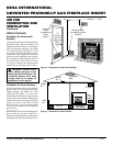
UNVENTED PROPANE/LP GAS FIREPLACE INSERT
DESA INTERNATIONAL
For more information, visit www.desatech.com
CONNECTING FIREPLACE
INSERT TO GAS SUPPLY
CAUTION: Use only new, black
iron or steel pipe. Internally-tinned
copper tubing may be used in cer-
tain areas. Check your local codes.
Use pipe of 1/2" diameter or greater
to allow proper gas volume to fire-
place. If pipe is too small, undue
loss of pressure will occur.
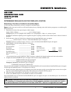
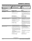
Installation must include a equipment shutoff
valve, and plugged 1/8" NPT tap. Locate
NPT tap within reach for test gauge hook up.
NPT tap must be upstream from fireplace
insert (see Figure 18).
IMPORTANT:
Install equipment shutoff
valve in an accessible location. The equip-
ment shutoff valve is for turning on or
shutting off the gas to the appliance.
INSTALLING GAS PIPING TO
FIREPLACE LOCATION
WARNING: A qualified ser-
vice person must connect fire-
place insert to gas supply. Fol-
low all local codes.
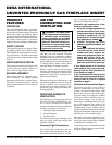
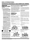
CAUTION: Never connect
heater directly to the propane/LP
supply. This heater requires an ex-
ternal regulator (not supplied). In-
stall the external regulator between
the heater and propane/LP supply.
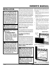
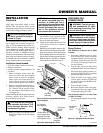
Figure 17 - External Regulator with Vent
Pointing Down
Propane/LP
Supply
Tank
External
Regulator
Vent
Pointing
Down
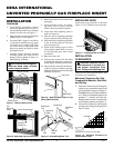
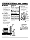
CSA Design-Certified
Equipment Shutoff Valve
With 1/8" NPT Tap*
3" Minimum
Supplied
Flexible Gas
Line
Installation Items Needed
Before installing fireplace insert, make sure
you have the items listed below.
• external regulator (supplied by installer)
• piping (check local codes)
• sealant (resistant to propane/LP gas)
• equipment shutoff valve *
• test gauge connection *
• sediment trap
• tee joint
• pipe wrench
• approved flexible gas line with gas connec-
tor (if allowed by local codes) (not provided)
* An CSA design-certified equipment
shutoff valve with 1/8" NPT tap is an ac-
ceptable alternative to test gauge connec-
tion. Purchase the optional CSA design-
certified equipment shutoff valve from your
dealer. See Accessories, page 26.
INSTALLATION
Continued
From External
Regulator (11"
W.C. to 14"
W.C. Pressure)
Mantel Clearances for Insert
Installation
If there is a mantel above masonry fireplace,
you must meet minimum clearance between
mantel shelf and top of fireplace opening.
Figure 18 - Gas Connection
Cap Pipe Tee
Nipple Joint
Sediment Trap
* Purchase the optional CSA design-certi-
fied equipment shutoff valve from your
dealer. See Accessories, page 26.
NOTICE: If your installation does
not meet the minimum clearances
shown, you must do one of the
following:
• raise the mantel to an accept-
able height
• remove the mantel
WARNING: Never connect
fireplace insert to private (non-
utility) gas wells. This gas is com-
monly known as wellhead gas.
NOTICE: Surface temperatures of
adjacent walls and mantels be-
come hot during operation. Walls
and mantels above the firebox
may become hot to the touch. If
installed properly, these tempera-
tures meet the requirements of
the national product standard.
Follow all minimum clearances
shown in this manual.
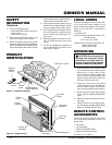
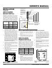
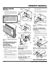
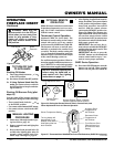
7. Attach fireplace to wall studs using
nails or wood screws through holes in
nailing flange (see Figure 16).
8. Check all gas connections for leaks. See
Checking Gas Connections, pages 11
and 12.
9. Install surround kit. See Installing Sur-
round Kit (GS38 or GS43), pages 8
and 9.
The installer must supply an external regu-
lator. The external regulator will reduce
incoming gas pressure. You must reduce
incoming gas pressure to between 11 and
14 inches of water. If you do not reduce
incoming gas pressure, heater regulator
damage could occur. Install external regu-
lator with the vent pointing down as shown
in Figure 17. Pointing the vent down pro-
tects it from freezing rain or sleet.
Figure 16 - Attaching Fireplace Instert to
Wall Studs
Nails or
Wood
Screws
Nailing
Flanges