


Special offers from our partners!

Find Replacement BBQ Parts for 20,308 Models. Repair your BBQ today.
www.desatech.com
112301-01D8
FIREPLACE
INSTALLATION
Continued
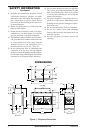
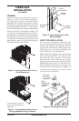
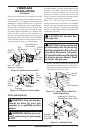
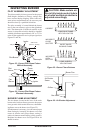
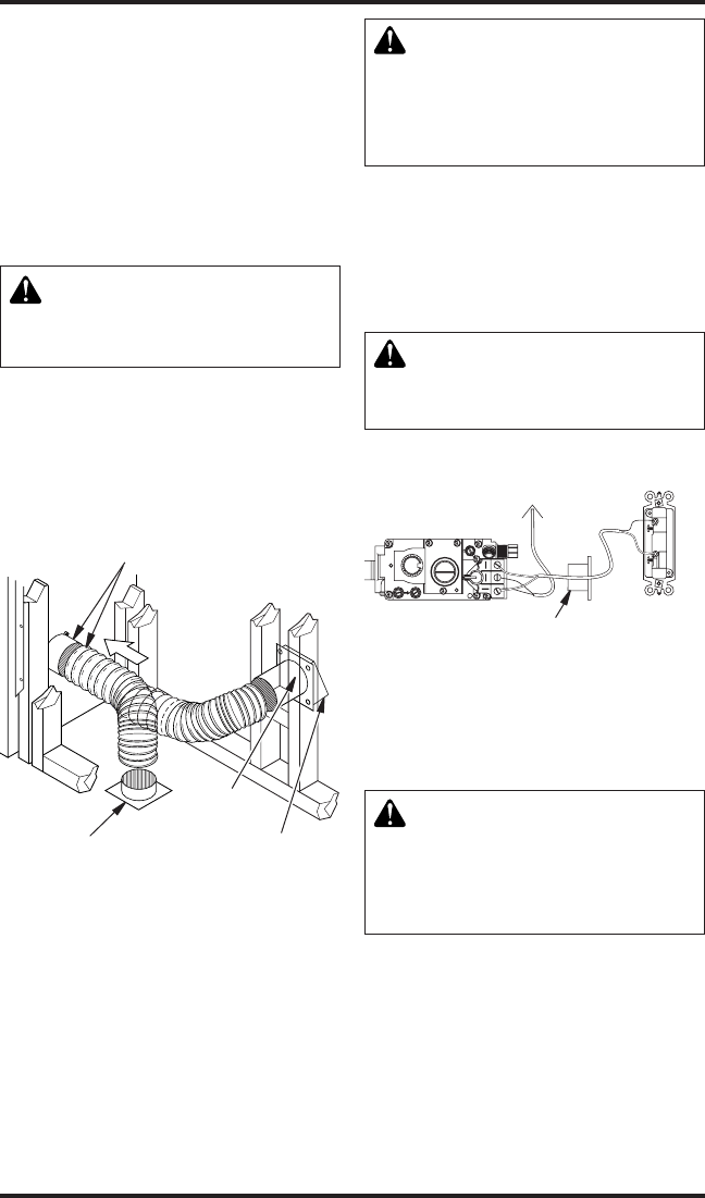
OPTIONAL OUTSIDE AIR KIT
The installation of an outside air kit should be
completed during the rough framing of the re-
place due to the nature of it's location. Outside
combustion air is accessed through a vented
crawl space.
CAUTION: Air inlet ducts
attic space.
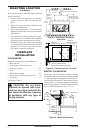
Avoid installing outside air eyebrow in areas where
inlet opening may be blocked by snow, bushes or
other obstacles (see Figure 10).
The maximum height for the air inlet termination
cannot exceed 3 feet below the B-vent termination
exhaust height.
Figure 10 - Outside Air Kit
Secure to Collars with Duct Tape or
Screws
Air Inlet
Location
Must Allow
For Bushes
or Snow
Vent Hood
Required for
Wall Installation
Air Inlet
Eyebrow
Vented Crawl Space
(Check Local Codes
Before Installing in a
Vented Crawl Space)
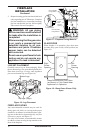
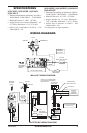
WALL SWITCH INSTALLATION
The electronic version uses a 24 VAC current sup-
plied from a transformer mounted on the ignition
module and is prewired for easy connection to a
wall switch. The millivolt version uses a self-gen-
erated millivolt current that allows you to activate
the gas control valve directly without the use of
normal household electricity. Both versions are
supplied with a wall switch kit for ready connec-
tion and mounting.
CAUTION: Do not connect
repair.
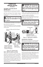
Connect 18 ga. wires from wall switch to gas
control valve terminals marked TH and TPTH
or to ignition module using pigtails and wire nut
connectors supplied with appliance.
Note: If any of the original supplied wire must be
replaced, use type 18 AWG-105 C (25 ft. maxi-
mum length) or equivalent only.
-
GAS SUPPLY TESTING
Note: This section is intended as a guide for quali-
ed technicians installing gas to this appliance.
CAUTION: Do not connect
-
The appliance and its individual shutoff valve must
be disconnected from the gas supply piping system
during any pressure testing of that system at test
pressures in excess of 1/2 psig (3.5 kPa).
The appliance must be isolated from the gas sup-
ply piping system by closing its individual manual
shutoff valve during any pressure testing of the gas
supply piping system at test pressures equal to or
less than 1/2 psig (3.5 kPa).
Figure 11 - Wall Switch Installation
O
F
P
I
L
O
T
O
N
F
T
O
I
P
L
7
TP
T
H
TP
TH
Wall Switch
(Supplied)
Back View
To Thermopile
Route Millivolt Wires
(Supplied) Through
Electrical Conduit Bushing