


Special offers from our partners!

Find Replacement BBQ Parts for 20,308 Models. Repair your BBQ today.
www.desatech.com
112301-01D 13
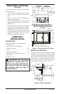
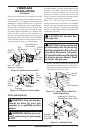
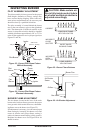
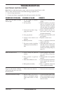
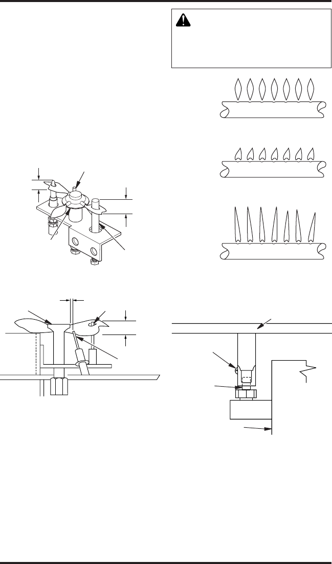
Figure 23 - Correct Pilot Flame Pattern
Millivolt Assembly
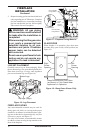
Figure 24 - Correct Pilot Flame Pattern
Electronic Assembly
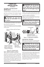
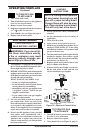
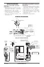
Figure 26 - Air Shutter Adjustment
Burner Pan
Air Shutter
Screw
Orice
Gas Valve
3/8" to 1/2"
1/8" to 1/4"
Pilot
Burner
Ignitor
Flame
Sensor
Pan
Burner
3/8" to 1/2"
(10 mm - 13 mm)
1/8" (3 mm)
Ignitor
Pilot Burner
Thermopile
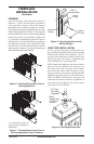
CORRECT
INCORRECT
CLOSE
SHUTTER
INCORRECT
OPEN
SHUTTER
LONG, BLUE FLAME
WITH YELLOW TIPS
SHORT, SHARP
BLOWING FLAME
LONG, UNEVEN
YELLOW FLAME
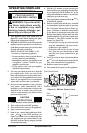
Figure 25 - Burner Flame Patterns
INSPECTING BURNER
PILOT ASSEMBLY ADjUSTMENT
The pilot assembly is factory preset for the proper
ame height. Alteration to factory settings may
have occurred during shipping. If this is the case,
some minor readjustments may be necessary and
should be done by a qualied technician.
The pilot assembly is located behind the burner
next to the rear refractory piece at the right-hand
side. The thermopile (in millivolt models) or the
sensor (in electronic models) should be engulfed
with the pilot ame approximately 3/8" to 1/2" in
order for the regulator to receive proper signal (see
Figures 23 and 24).
BURNER FLAME ADjUSTMENT
The air shutter, located at the base of the main
burner tube, has been factory preset to the proper
air to gas ratio which results in an even, clean burn-
ing ame across the burner (see Figure 25).
If readjustment is necessary, you can restore proper
ame setting by loosening air shutter screw and
rotate air shutter until proper ame setting is
achieved (shutters normal setting is fully opened).
Retighten air shutter screw. See Figure 26 for air
shutter location.
-
air shutter and that air shutter is