


Special offers from our partners!

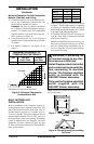
Find Replacement BBQ Parts for 20,308 Models. Repair your BBQ today.

www.desatech.com
112462-01B 15
3
2
1
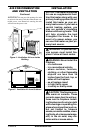
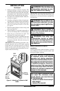
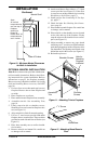
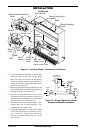
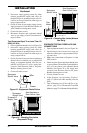
Figure 15 - Installing Blower (Thermostat Unit Shown)
Wire Harness
Blower Bracket Assembly
Screw
Wire
Harness
Switch
Baffle
Wiring Routing Hole
in Baffle
Switch
Plate
Blue
Red
Rear Fan
Switch Cover
Snap
Bushing
Power Cord
Black
Blower Mounting
Holes
Lower Louver Door
Front Fan
Switch
Cover
INSTALLATION
Continued
6. In top of the fireplace cabinet, locate the four
mounting holes on the outer casing. Align
these four holes with those on the blower
bracket assembly. Attach blower bracket as-
sembly to the outer casing with 4 #10 screws
provided (see Figure 15).
7. Route the wire harness through the hole in left
side of baffle. Pull wire harness through lower
opening of firebox (see Figure 15).
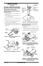
8. Insert the 4 wire harnesses into one of the
round holes in the rear of the fan switch cover
and through the rectangular hole on front of
the fan switch cover (see Figure 15).
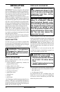
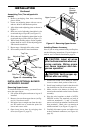
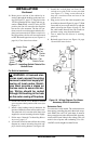
8. Reconnect red wire to switch position 3. Re-
connect blue wire to switch position 1. Re-
connect green and white wires.
9. Install the switch plate on front of fan switch
cover with 2 #10 screws provided (see Fig-
ure 17, page 16). Using screw removed in
step one, reconnect front and rear of fan
switch cover.
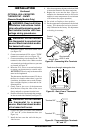
Figure 16 - Wiring Diagram For Blower
Accessory Standard Installation
Red
Red
Fan Switch
(Auto/Off/On)
Blue
Blue
Thermostat
Switch
(N.O.)
Green
White
Green
White
On
110/115
V.A.C.
Blower
Motor
Black
Off
1
2
3
Auto