


Special offers from our partners!

Find Replacement BBQ Parts for 20,308 Models. Repair your BBQ today.
www.desatech.com 112462-01B
14
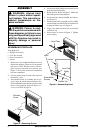
Assembling Trim (Trim shipped with
mantel)
1. Remove packaging from three remaining
pieces of trim.
2. Locate two adjusting plates with set screws,
and two shims in the hardware packet.
3. Align shim under adjusting plate as shown in
Figure 13.
4. Slide one end of adjusting plate/shim in slot
on mitered edge of top trim (see Figure 13).
5. Slide other end of adjusting plate/shim in slot
on mitered edge of side trim (see Figure 13).
6. While firmly holding edges of trim together,
tighten both set screws on the adjusting plate
with slotted screwdriver.
7. Repeat steps 1 through 6 for other corner.
8. Set assembly aside for later installation.
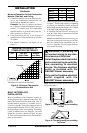
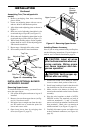
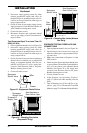
Figure 13 - Assembling Trim
Side Trim
Top Trim
Mitered Edge
Shim
Set
Screws
Adjusting Plate
Slot
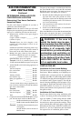
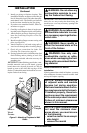
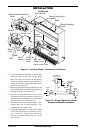
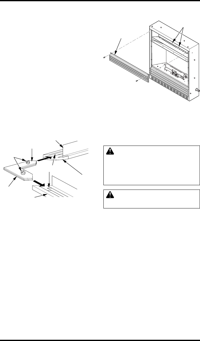
Figure 14 - Removing Upper Louver
Blower
Bracket
Mounting
Holes
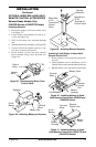
INSTALLING OPTIONAL BLOWER
ACCESSORY GA3450T
Removing Upper Louver
To install the blower accessory, you must first re-
move the upper louver.
1. Lift screen off fireplace and remove log set if
installed.
2. Remove 4 screws from upper louver (see Fig-
ure 14). Save these screws.
3. Pull upper louver straight out from the cabi-
net. Be careful not to scratch the paint. Set
louver and screws aside.
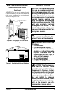
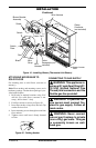
4. Open lower louver door by swinging door
down (see Figure 15, page 15).
Upper Louver
INSTALLATION
Continued
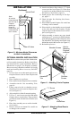
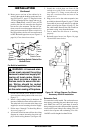
Installing Blower Accessory
Note: If you are using a mantel with your fireplace,
use the following instructions. If your fireplace is
built-in, see For Built-In Installation, page 16.
CAUTION: Label all wires
prior to disconnection when ser-
vicing controls. Wiring errors
can cause improper and dan-
gerous operation.
CAUTION: Verify proper op-
eration after servicing.
1. Locate fan switch cover. Remover bottom
screw to remove back portion of the cover.
2. Install snap bushings found in hardware kit
into both holes in rear of fan switch cover.
3. Make sure the wire harness is firmly con-
nected to the terminals on the blower bracket
assembly.
4. Note the wire locations on back of AUTO/
OFF/ON switch. The terminals on back of
switch are numbered 1, 2, and 3. Carefully
remove red wire from terminal 3 and blue wire
from terminal 1. Black wire can remain on
middle terminal 2 (see Figure 15, page 15).
5. Carefully disconnect green and white wires
at their insulated connectors (see Figure 16,
page 15).