


Special offers from our partners!

Find Replacement BBQ Parts for 20,308 Models. Repair your BBQ today.
www.desatech.com
111244-01E
12
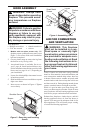
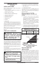
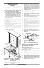
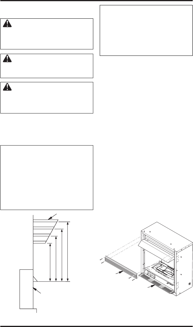
15"
18"
21"
23"
2
1
/
2
"
6"
8"
10"
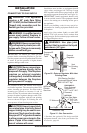
Note:
A
ll vertical
measurements
are from top of
fireplace
opening to
bottom of
mantel shelf. All
measurements
are in inches.
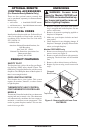
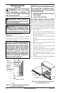
INSTALLATION
Continued
WARNING: Do not allow
noncombustible materials to
cover any necessary openings
like louvered slots.
WARNING: Never modify or
cover the louvered slots on the
front of the firebox.
WARNING: Use only noncom-
bustible mortar or adhesives when
overlapping the front facing with
noncombustible facing material.
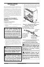
Mantel Clearances for Built-In
Installation
If placing mantel above built-in fireplace, you must
meet minimum clearance between mantel shelf and
top of fireplace opening.
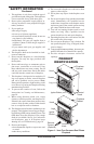
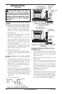
NOTICE: Surface temperatures
of adjacent walls and mantels be-
come hot during operation. Walls
and mantels above the firebox
may become hot to the touch.
If installed properly, these tem-
peratures meet the requirement
of the national product standard.
Follow all minimum clearances
shown in this manual.
Figure 11 - Minimum Mantel Clearances
for Built-In Installation
Mantel Shelf
Side of Firebox
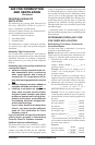
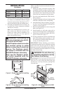
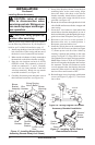
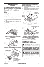
Figure 12 - Removing Top Louver and
Opening Bottom Louver
O
F
F
P
I
L
O
T
O
N
H
I
L
O
Top
Louver
Bottom Louver
NOTICE: If your installation does
not meet the minimum clear
-
ances shown, you must do one
of the following:
• raise the mantel to an accept-
able height
• remove the mantel
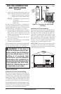
OPTIONAL MANTEL INSTALLATION
Note: Refer to instructions provided with the
mantel for assembly instructions. Refer to the
following instructions for system installation.
Refer to instructions on page 6 for hood assembly.
Blower accessory should be installed if it is being
used (see Installing Optional Blower Accessory
GA3450TA,
page 13).
1. Unscrew four screws that attach top louver to
fireplace. Remove louver from fireplace and
set aside (see Figure 12).
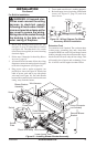
2. Place base assembly next to wall at installation
location.
3.
Place fireplace on wood base (see Figure 13,
page 13).
4. Place mantel around fireplace on base (see
Figure 13, page 13).
5. Assemble perimeter trim kit. See
Assembling
Perimeter Trim,
page 13.
6. Firmly snap perimeter trim kit on shoulder
screws. Shoulder screws are located on fire
-
place cabinet (see Figure 13, page 13).
7. Align perimeter trim kit for flush fit around
opening.
8. Center mantel left to right on base making sure
mantel is flush against wall.