


Special offers from our partners!

Find Replacement BBQ Parts for 20,308 Models. Repair your BBQ today.
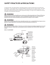
Tools required: Phillips screwdriver.
Important!
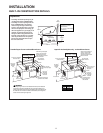
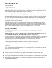
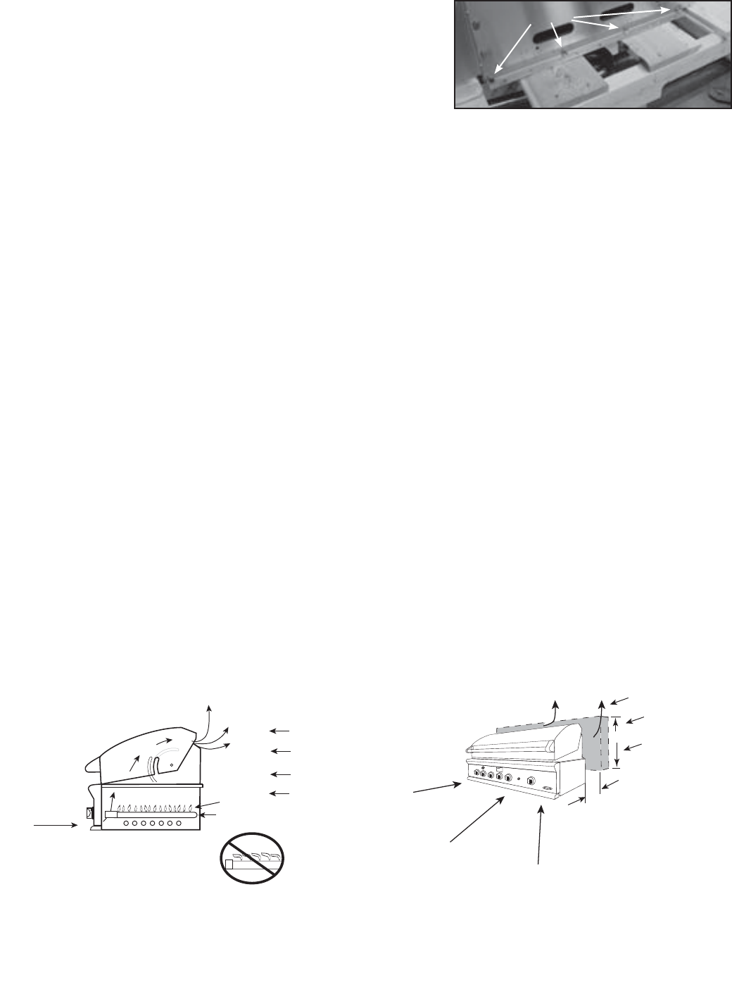
Before installation, remove shipping brackets from the grill. To
do so, loosen the 4 screws on the bottom sides of the grill which
hold the brackets to the grill. Slide the shipping brackets off and
retighten the screws.
Remove all internal packaging and adhesive residue. To remove
stubborn residue, use rubbing alcohol or a commercially avail-
able adhesive remover.
Packing elements (i.e. plastic bags, polystyrene foam, nails, packing straps, etc.) should not be left around
within easy reach of children, as these may cause serious injuries.
LOCATION:
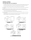
When determining a suitable location take into account concerns such as exposure to wind, proximity to traffic
paths and keeping any gas or electrical supply lines as short as possible and away from heat sources. Locate the
grill only in a well ventilated area. Do not build the grill under overhead unprotected combustible construction.
Never locate the grill in a building, garage, breezeway, shed or other such enclosed areas. See following page
for definition and illustration of outdoor areas. During heavy use, the grill will produce a lot of heat and smoke.
Ensure there is adequate area for it to dissipate.
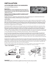
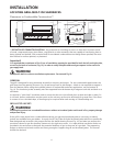
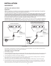
If locating the grill in a windy area, try to locate the grill so the prevailing wind will blow air at the front of the
grill as shown in Fig. 02. This will assist the grill in venting hot air thru the back of the grill. In addition, this will
help keep any smoke from blowing at someone who is cooking on the grill. If you have to locate the grill in a
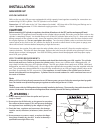
windy area where the prevailing wind is at the rear of the grill, a windbreak must be installed. The windbreak
should be made such that it will block wind from entering the exhaust vent in the rear of the unit as shown in Fig.
02. Location of the windbreak relative to rear of the grill must adhere to the clearances specified for combustible
or non-combustible construction as defined in these instructions. Refer to following pages.
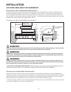
As a high-performance gas appliance, your grill requires significant amounts of air to support the combustion
process. Your grill is designed to take air in through the valve panel area, and send the exhaust products out
through the exhaust gap at the rear of the hood. Using your grill in windy conditions can disrupt the proper flow
of air though your grill, leading to reduced performance, or in certain severe cases, causing heat buildup in the
valve panel area. This can lead to problems such as having the knobs melt, or burn hazards when the valve panel
surfaces become too hot to touch.
During high wind conditions, it is best if you don’t use your grill. If you live in an area that is subject to frequent
high winds, or a steady directional wind, then the installation of a suitable windbreak may be advised. If you have
a grilling cart, it is best to position the unit so the prevailing wind blows into the valve panel, thus supporting the
proper airflow. Winds hitting the back of the grill directly are the most likely to cause problems, although wind
blowing along the exhaust gap in the rear can also be problematic.
Please note that damage to your grill resulting from use in windy conditions, such as melted knobs or igniter
wires, or valve panel discoloration from heat build-up, are excluded from warranty coverage.
Important!
Gas fittings, regulator, and installer supplied shut-off valves must be easily accessible.
INSTALLATION
LOCATING GRILL/BUILTIN CLEARANCES
8
PREFERRED
AIR FLOW
GRILL EXHAUST
EXHAUST
FLAME
BURNER
Wind hitting the
grill while in use,
especially winds
blowing into or
across this hood
gap, can cause
poor performance
and in some cases
can cause the
control panel to
get dangerously
hot.
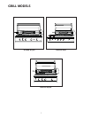
GRILL PLACEMENT
FIG. 1
Shipping Brackets
If wind is an
issue, a wind
screen should
be added. The
wind screen
should be
higher than
the top of the
opening in the
back of the
grill, with a
minimum
clearance of
76 mm (for
non-combusti
bles) or 310
mm (for
combustibles)
from the back
of the grill
WIND SCREEN
WIND
min. 381 mm
min. 76 mm
for non-
combustibles
min. 310 mm for
combustibles
WIND
WIND
PRIMARY
INTAKE
AIR FLOW
EXHAUST VENT FLOW
FLAME LIFT
FIG. 2