


Special offers from our partners!

Find Replacement BBQ Parts for 20,308 Models. Repair your BBQ today.
GAS REQUIREMENT
Verify the type of gas supply to be used, either natural or LP, and make sure the marking on the appliance rating
plate agrees with that of the supply. The rating plate is located on the bottom of the outdoor appliance. Never
connect an unregulated gas line to the appliance. You must use the gas regulator provided with the unit even if
the supply is controlled.
An installer-supplied gas shut-off valve must be installed in an easily accessible location. All installer supplied
parts must conform to local codes, or in the absence of local codes, with the National Electrical Code, ANSI/NFPA
70 or the Canadian Electrical Code, CSA C22.1, and the National Fuel Gas Code, ANSI Z223.1 or CAN/CGA-B149.1
Natural Gas Installation Code or CAN/CGA-B149.2 Propane Installation Code.
All pipe sealants must be an ap proved type and resistant to the actions of LP gases. Never use pipe sealant on
flare fittings. All gas connections should be made by a qualified technician and in accordance with local codes
and ordinances. In the absence of local codes, the installation must comply with the National Fuel Gas Code,
ANSI Z223.1. Gas conversion kits are available from the factory. When ordering gas conversion kits, have the
model number, and the type of gas (natural or LP) from your outdoor appliance.
TOTAL GAS CONSUMPTION OF THE OUTDOOR APPLIANCE WITH ALL BURNERS ON HI/
SEAR:
BFG-30G - 50,000 Btu/hr BFG-30BGD - 49,000 Btu/hr BFG-30BS - 34,000 Btu/hr
The appliance and its individual shut-off valve must be disconnected from the gas supply piping system during
any pressure testing of that system at test pressures in excess of 1/2 PSIG (3.5 kPa.) The appliance must be iso-
lated from the gas supply piping system by closing its individual manual shut-off valve during any pressure test-
ing of the gas supply piping system at test pressures equal to or less than 1/2 PSIG (3.5 kPa.). The installation of
this appliance must conform with local codes or, in the absence of local codes, with the National Fuel Gas Code,
ANSI Z223.1. Installation in Can ada must be in accordance with the Standard Can1-b149.1 and/or .2 (installation
code for gas burning appliances and equipment) and
local codes.
NATURAL GAS HOOK UP: THIS TYPE OF
CONNECTION SHOULD BE PERFORMED BY A
CERTIFIED OR LICENSED TECHNICIAN ONLY.
Connection: 1/2” NPT male with 3/8” flare adapter.
Operating pressure: 4.0” W.C. Supply pressure: 5”
to 14” water column. If in excess of 14” W.C., a step-
down regulator is required. Check with your local
gas utility company or local codes for instructions on
installing gas supply lines. Be sure to check on type
and size of run, and how deep to bury the line. If the
gas line is too small, the outdoor appliance will not
function properly. Any joint sealant used must be
an approved type and be resistive to the actions of
natural gases.
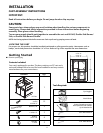
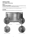
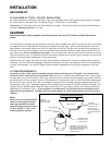
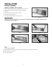
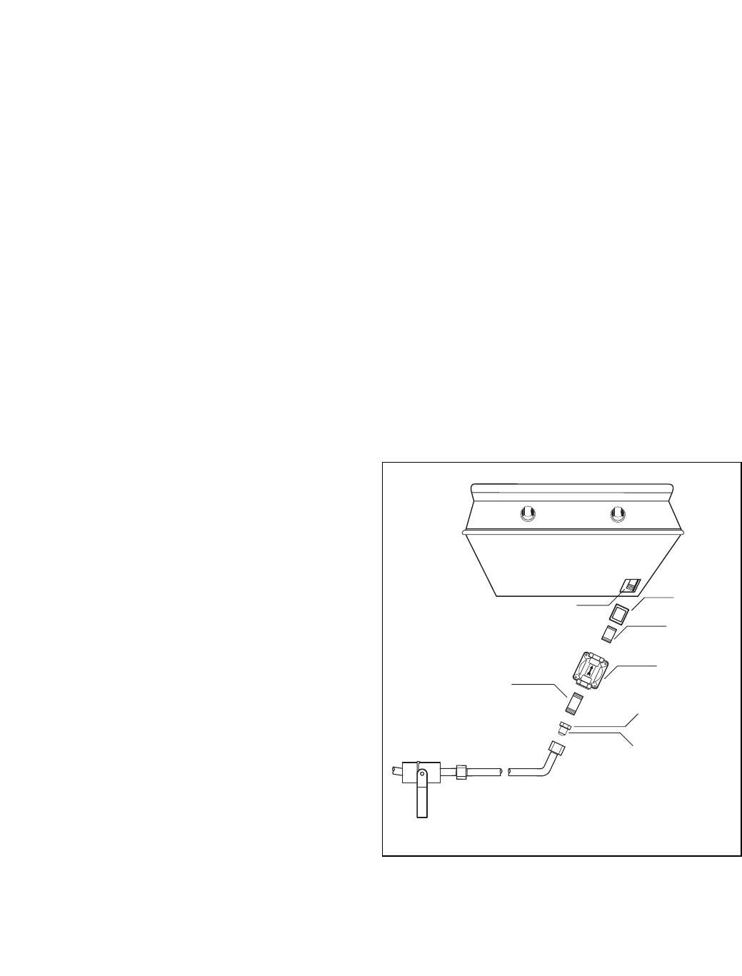
TO HOOKUP THE FITTINGS SUPPLIED
WITH THE OUTDOOR APPLIANCE:
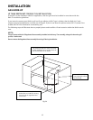
Assemble as shown (Fig. 22). Use threading com-
pound on male threads only. Do not use threading
compound on the male end of the 1/2” NPT to 3/8
flare adapter. Use a second pipe wrench to hold the
outdoor appliance inlet pipe to avoid shifting any
internal gas lines of the outdoor appliance. Ensure
that the regulator arrow points in the direction of gas
flow towards the unit, away from the supply. Do not forget to place the installer-supplied gas valve in an acces-
sible location.
Bottom of unit
Threading compound
must be resistant to LP gas
Coupling
1/2” NPT x
2.0”
Nipple
Regulator
4.0" W.C.
Adapter 1/2” NPT
to 3/8” flare fitting
Do not put threading
compound on these
threads
*Installation must conform with local
codes or with the National Fuel Gas Code
ANSI Z223.1 or the CAN/CGA-B149.2
Propane Installation Code
Installer supplied shut-off
valve must be easily
accessible*
1/2” NPT x 5.0”
Nipple
Fig. 22 Natural Gas
INSTALLATION
GAS HOOKUP
16