


Special offers from our partners!

Find Replacement BBQ Parts for 20,308 Models. Repair your BBQ today.
9
INSTALLATION
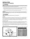
LOCATING BUILTIN CLEARANCES
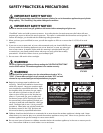
WARNING!
The appliances are designed to function in an open area. Recommended minimum clearances should be maintained
to all surfaces (combustible* and noncombustible**) for optimum performance. Noncombustible** material within
the minimum clearance area could result in discoloration or deterioration.
*DEFINITION OF COMBUSTIBLE MATERIAL - Any materials of a building structure or decorative structure made of wood, compressed
paper, plant fibers, stucco or other materials that are capable of transferring heat or being ignited and burned. Such material shall be
considered combustible even though flame-proofed, fire-retardant treated, or painted surface or plastered.
**DEFINITION OF Noncombustible MATERIAL - Material which is not capable of being ignited and burned, such as materials consisting
entirely of, or a combination of, steel, iron, brick, tile, concrete, slate, and plaster (which is unpainted).
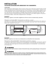
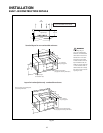
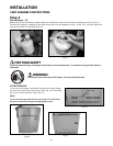
Important!
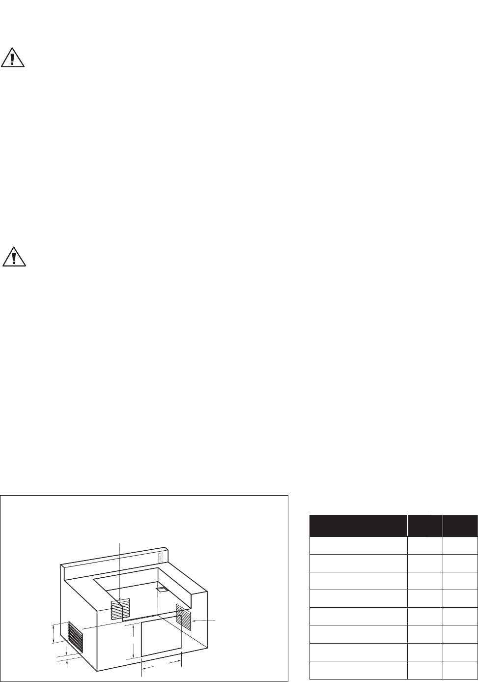
It is recommended that a minimum of 10 sq. inches of ventilation opening be provided for both the left and
right sides, as well as the back of enclosure (Fig. 02), in order to safely dissipate unburned gas vapors in the
event of a gas supply leak.
WARNING!
Note specific built-in enclosure ventilation requirements. See text and Fig. 02.
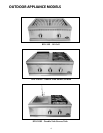
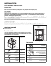
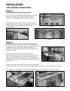
GENERAL
The outdoor appliance is designed for easy placement into masonry enclosures. For non-combustible applica-
tions the outdoor appliance drops into the opening shown in Fig. 03 and hangs from its side flanges. The deck
must be level and flat. A deck is not required to support the unit from the bottom. When using the insulated
jacket in a combustible enclosure application, see the bottom of Fig. 03. The jacket assembly must be supported
from the bottom by a ledge on each side or a solid deck beneath the entire insulated jacket.
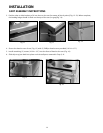
INSULATED JACKET:
If the outdoor appliance is to be placed into a combustible enclosure, an approved insulated jacket is required
and is available from your dealer. Insulated jacket is not required for BFG-30BS Side Burner Sink Model. Use only
the DCS insulated jacket (p/n #70859) which has specifically been designed and tested for this purpose.
Review the detail drawing shown (Fig. 03) and take into account the provisions shown for gas line hook-up clear-
ance in the right rear corner. It is recommended that ventilation holes are provided in the enclosure to eliminate
the potential build-up of gas in the event of a gas leak. The supporting ledges or deck must be level and flat. The
counter should also be level.
Fig. 02
Ventilation Requirements:
10 in.
2
Min. ventilation
left hand side
10 in.
2
Min. ventilation
on the right hand side
10 in.
2
Min. ventilation
on the back side
1" Min.
A
B
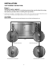
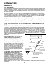
CUTOUT DIMENSIONS OF MATCHING ACCESS DOORS/DRAWERS:
AB
22"
28"
34"
46"
22"
34"
28"
46"
20"
20"
20"
20"
20"
20"
20"
20"
ACCESS DOOR/
DRAWER MODELS
ADN 20X24
ADN 20X30
ADN 20X36
ADN 20X48
ADR24
ADR36
ADR30
ADR48
Note: not drawn to scale
Opening for
access doors/drawers