


Special offers from our partners!

Find Replacement BBQ Parts for 20,308 Models. Repair your BBQ today.

7
Vermont Castings EWF30
20008662
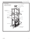
Planning Information
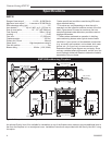
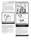
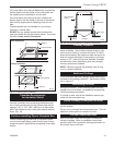
Determine how the chimney will be run, length of run
and chimney components required to complete the
job. (Fig. 4) Never install a chimney below minimum
heights.
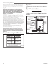
In planning a chimney system, it is important to know:
1. The height of a chimney is measured from the hearth
to the exit point on the termination.
2. A chimney cannot be offset more than 30° from a
vertical plane.
3. A chimney may run straight up or it may be neces-
sary to offset it to avoid obstructions.
4. The maximum length of an angled run (total chimney
system) is 20 feet.
5. No more than 2 offsets (4 total 30° elbows in U.S./or
2 total 45° elbows in Canada) per fireplace may be
used.
6. A guy wire stabilizer is required for chimneys extend
-
ing more than 6’ (1.8m) above a roof line.
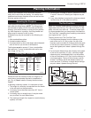
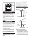
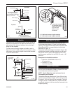
The Ten Foot Rule
Major U.S. building codes specify a minimum chimney
height above the roof top. The “Ten Foot Rule” is a fire
safety rule and not a draft rule. To ensure proper draft,
it is recommended that you always meet or exceed the
“Ten Foot Rule,” especially when installing a termination
on a high pitch roof. (Fig. 5)
The key points of the “Ten Foot Rule” are:
1. If the horizontal distance from the chimney to the
peak of the roof is 10’ (3m) or less, the top of the
chimney must be at least 2’ (610mm) above the peak
of the roof, but never less than 3’ (914mm) in height
above the highest point where it passes through the
roof.
2. If a horizontal distance from the chimney to the peak
of the roof is more than 10’ (3m), a chimney height
reference point is established that is on the surface
of the roof a distance of 10’ (3m) from the chimney in
a horizontal plane. The top of the chimney must be
at least 2’ (610mm) above the reference point, but
never less than 3’ (914mm) in height above the high-
est point where it passes through the roof.
2' Min.
2' Min.
3'
Min.
0 To 10'
3'
Min.
0 To 10'
AC246
4/1/96
Reference
Point
AC246
Fig. 5 Ten Foot Rule illustration.
Planning an installation is very important to ensure
safety and to save time and money. An installer must
predetermine where a fireplace will be set and how the
chimney system will be run.
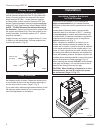
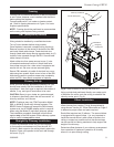
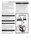
Mounting the Fireplace
The fireplace is shipped with lifting handles attached to
each side with lifting straps. NOTE: The lifting straps
are intended for ligting unit off of the skid and final po-
sitioning. Unit should remain on skid until final position-
ing. After fireplace is in position, the lifting handle and
straps may be removed or left in place.
A fireplace may only be mounted on the following sur
-
faces:
1. A flat combustible surface.
2. A raised wooden platform.
3. A concrete block or other solid object placed beneath
each of the four (4) corners of the fireplace.
The fireplace must be spaced 1” from a combustible
back wall and 1” from a combustible side wall or sup-
port. (Page 13, Fig. 17)
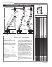
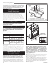
Planning the Chimney Run
L
1
L
1
L
T
TOTAL
LENGTH
(L
T
)
INSTALLED
LENGTH
(L
1
)
"
"
"
"
"
"
"
"
FP288A
MBUF-INSTALLED LENGTH
Triple wall
1/28/99 djt
TRIPLE
WALL
81
818
83
84
FP288a
Fig. 4 Installed lengths of chimney sections.
TOTAL INSTALLED
TRIPLE LENGTH LENGTH
WALL (L
T
) (L
1
)
SK81 11¹⁄₂” 10¹⁄₂”
SK818 17
¹⁄₂” 16¹⁄₂”
SK83 35
¹⁄₂” 34¹⁄₂”
SK84 47
¹⁄₂” 46¹⁄₂”