


Special offers from our partners!

Find Replacement BBQ Parts for 20,308 Models. Repair your BBQ today.

15
Vermont Castings EWF30
20008662
FP531
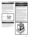
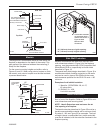
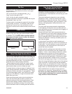
Fireplace surround detail
1/29/99 djt
Must be sealed with
noncombustible material
Mantel Shelf
Side View
Finished Wall
2 x 4 Stud
Standoff
Cast Front
See mantel drawing for
shelf-to-grille dimension
1” (25mm)
Fireplace
Front (Steel)
2 x 4 Stud
FP1200
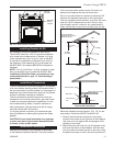
Fig. 20 Finishing materials placement.
Brick Ledge
Noncombustible Finish Mate
-
rial Only in this Area
Top View
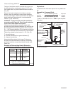
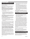
Mantels
The height that a combustible mantel is fitted above the
fireplace is dependent on the depth of the mantel. This
also applies to the distance between the mantel leg (if
fitted) and the fireplace.
For the correct mounting heights and widths, refer to
Figures 21 and 22. When using paint or lacquer to finish
the mantel, such paint or lacquer must be heat resistant
to prevent discoloration.
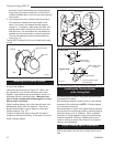
Side Wall Protection
Adjacent combustible side walls that are within mini-
mum dimensions shown in Figure 24 of the fireplace
opening must be protected with CFM Corporation Wall
Shield Model SP40 or a specifically built wall shield
described in Figure 19.
The special wall shield design described in Figure 19 is
an alternate method of adding protection to side walls
and can be used in place of the SP40 with the same
wall clearances specified for the SP40. Rt must =1.85
minimum.
Examples of wall shield insulation:
1. Manville - CERAFORM 126, K=.27,
1/2 inches thick
2. EH2416, K = .458,
1 inch thick required.
Hearth Installation
A hearth extension is required to protect a combustible
floor in front of the fireplace. Refer to Figure 25 for mini-
mum dimensions and mounting detail.
NOTE: Hearth Extension must not cover the air
inlet opening of a fireplace.
The hearth extension described in Figure 25 must be a
durable noncombustible material with a minimum (total)
Rt value of 1.09; see Figure 23 for examples. The over-
all height (above a combustible floor), depth and width
must be as indicated, with the extension centered to the
fireplace opening.
FP1398
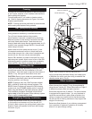
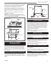
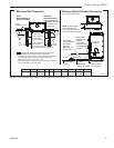
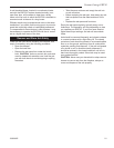
Fig. 21 Combustible mantel minimum opening.
FP1398
wood mantels
8/18/03 djt
6"
(159mm)
Min.
12"
(305mm)
Min.
1"
(38mm)
12"
(305mm)
Max.
Combustiible
Mantel and
Trim
Finished Wall
Header
Standoff
Noncombustible
Material
Brick Ledge
GrilleOpening
Fireplace
Front
MA81
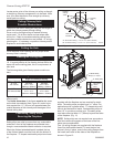
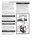
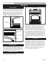
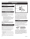
Fig. 22 Combustible mantel clearances.
MA81
rev. 8/5/97
*
1"
Ref.
**
Combustible materials
are permitted within a
shaded area shown in
Figure 25 titled
Minimum Wall
Clearances
* 12” (305 mm) from top of grille opening.
** 6” (152 mm) from top of grille opening.