


Special offers from our partners!

Find Replacement BBQ Parts for 20,308 Models. Repair your BBQ today.

10
Vermont Castings EWF30
20008662
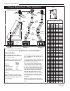
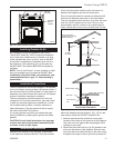
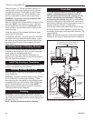
Locate center point of the chimney on ceiling as though
a straight up chimney arrangement is to be used. Mea-
sure your offset dimension from straight up chimney
center point on ceiling.
Ceiling Chimney Hole/
Possible Obstructions
The size of the hole in ceiling will vary with the angle at
which the chimney passes through ceiling.
Drive a nail up through ceiling at marked chimney
center point. Go to floor above and see where hole
will be cut. Check to see where existing ceiling joists
and other possible obstructions are located...i.e. wiring,
plumbing etc... If necessary, re-position chimney and/or
fireplace to avoid obstructions.
Cutting the Hole
Cover fireplace collar opening and cut proper sized
chimney hole in chimney.
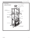
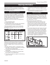
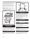
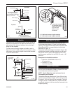
Framing the Ceiling Hole
Frame the ceiling chimney hole as shown in Figure
10. It is good practice to use framing lumber that is the
same size as the ceiling joists; this is a requirement at
attic level.
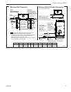
The following table gives firestop spacer model num
-
bers:
FP551
BR/BC
9/29/97
AB
AB
A "SK" Series framing = 14" X 14" (368 x 368 mm)
B "S" Series framing = 17" X 17" (445 x 445 mm)
Existing
Ceiling
Joists
Chimney
Hole
Ceiling
New Framing
Members
FP551b
Fig. 10 Typical frame for ceiling chimney hole.
The inside dimension of the frame must be the same
as the hole size selected from Figure 9 in order to pro-
vide required the 1¹⁄₂” (38 mm) air space between the
outside diameter of the chimney and the edges of the
framed ceiling hole.
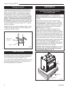
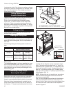
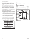
Positioning, Safety Strips,
Securing the Fireplace
Slide fireplace into position.
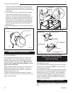
Safety strips are used to ensure that any combustible
materials in front of the fireplace are protected even
though a noncombustible hearth extension is required.
When the finished extended hearth is added, the top
of the finished hearth must be flush with the bottom of
the fireplace. “Z” shaped metal safety strips have been
supplied with the fireplace and are required for instal
-
lation. The safety strips provided have a 1” offset. For
applications with a greater offset, “Z” shaped strips will
have to be fabricated of metal. Overlap safety strips at
least 1/2” to provide a positive joint. The safety strips
must also extend at least 1¹⁄₂” (38mm) beyond the sides
of the fireplace. (Fig. 11)
NOTE: Safety strips are not required over noncombus-
tible floors where all supports at the base of the fire-
place are noncombustible.
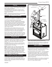
Four (4) nailing flanges are supplied with the fireplace
(found on the fireplace hearth). To level the box and
secure it firmly in place, remove the nailing flanges from
the hearth and install at the sides of the fireplace as
shown in Figure 12.
FP1564
Install metal
safety strips
3/05
“Z” Metal Safety
Strips (1 or 2 pcs.)
“Z” Safety Strip
Hearth Ext.
Fire-
place
Plat-
form
FP1564
1¹⁄₂”
(38mm)
1/2” Min.
Overlap
Fig. 11 Safety strip installation.
Decorative
Hearth
Face
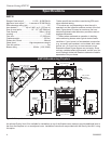
Fig. 9 Ceiling chimney hole sizes necessary for installing
firestop spacer.
Chimney Hole Size
Size of Chimney Vertical 30°
8" Flue SKFS2A SKFS6A
"SK" Series 14
¹⁄₂" x 14¹⁄₂" 14¹⁄₂" x 25¹⁄₂"
(368mm x 368mm) (368mm x 648mm)
8" Flue FS2A FS6A
"S" Series 3-Wall 17¹⁄₂" x 17¹⁄₂" 17⁷⁄₈" x 29⁵⁄₈"
(445mm x 445mm) (454mm x 753mm)
Angle of Chimney at Ceiling