


Special offers from our partners!

Find Replacement BBQ Parts for 20,308 Models. Repair your BBQ today.
11
Fixed Installation - Natural Gas
(Natural Gas installation should be carried out by a qualified gas fitter)
BeefEater Natural Gas barbecues are designed as low- pressure appliances (4.0” WC, 1.00KPa).
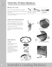
Fit the natural gas regulator supplied directly to the barbecue inlet located on the right side of the
appliance using either hard plaumbing, or a flexible hose connected to a bayonet point. Refer to AS
5601 or your local installation code for pipe sizing details. Secure all joints spanner tight but do not over-
tighten.
Test gas pressure by removing the last burner from the left hand side of the barbecue and attaching a
hose and pressure gauge to the end of the gas valve. Turn on 2 burners and check the pressure. Inlet
pressure should be 4.0” WC or 1.00 kPa.
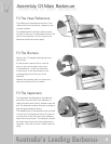
For mobile trolley installations that use flexible hosing to connect to natural gas, a chain or similar
restraining device must be fitted to prevent strain on the gas supply line. One end of the chain should
attach to the barbecue; the other end should attach to a fixed structural point close to where the hose
connects to the gas piping. The chain must be at least 30% shorter than the gas supply line. In this way,
if the barbecue is accidentally moved, the chain stops the barbecue from stretching the hose.
The barbecue appliance must be isolated from the gas supply piping system by closing its manual shutoff
valve during any pressure testing of the gas supply piping system.
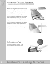
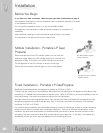
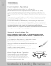
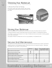
Right Wrong
Secure All Joints And Leak Test
Never use a naked flame to check for gas leaks. The gas leak testing procedure should be
conducted every time a gas cylinder is refilled and reconnected to the appliance, or after any
new gas connection is made.
In a small container, mix up a solution of water and detergent or soap. Mix the solution well.
For LPG make sure that the gas supply valve on the gas cylinder is turned on.
For Natural Gas make sure that the gas shutoff valve is on.
Make sure that the gas control valves on the appliance are all turned off.
Using a brush or spray bottle apply the solution to the gas line and each joint in
the gas line.
Bubbling of the solution will indicate that there is a leak present.
Re-tighten or re-seal any joints that are leaking.
If a leak persists contact your distributor or the manufacturer for assistance.
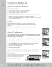
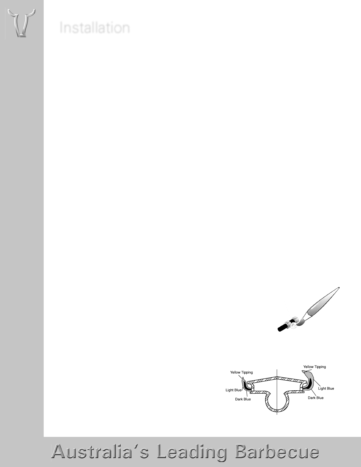
Check Proper Burner Operation
Following operating instructions light each burner and
check for a clear blue flame with just a tip of yellow.
Excess yellow tipping can be adjusted using the screw
the screw on the side of the burner. Turn the screw in an
anti-clockwise rotation to remove the yellow.
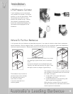
Installation