


Special offers from our partners!

Find Replacement BBQ Parts for 20,308 Models. Repair your BBQ today.
Buy Weber Grill Parts. It couldn't be easier. Find your Weber parts here.
3
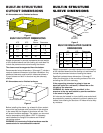
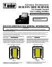
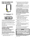
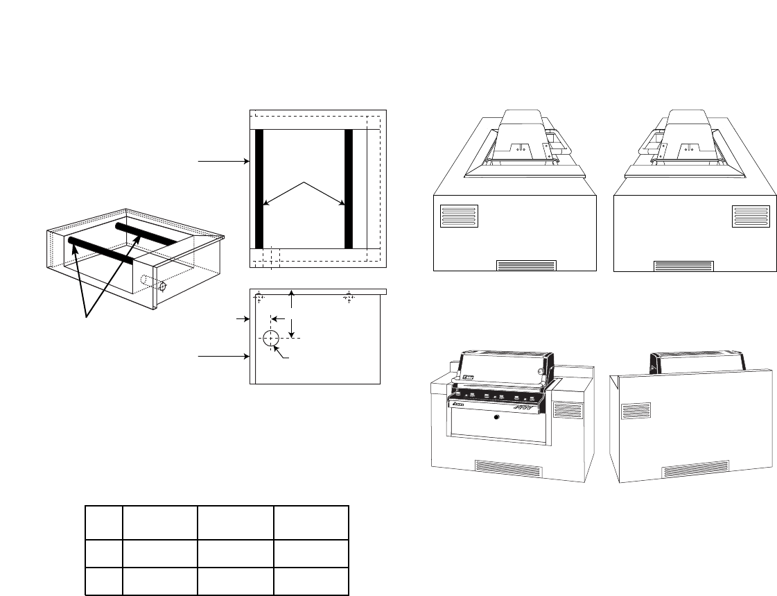
BUILT-IN SLEEVE GAS
LINE LOCATIONS
A
B
C
Support tubes
Front of sleeve
Front of sleeve
Plan view
Right side view
475 675 Tolerances
A 5.0” 5.0”
B 10.1” 10.1”
C 2.5” 2.5”
DIMENSIONS
+
1
⁄16
-
1
⁄16
+
1
⁄16
-
1
⁄16
+
1
⁄32
-
1
⁄32
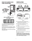
BUILT-IN SLEEVE GAS LINE
LOCATIONS
The dimensions shown indicate the location of the gas
line inlet flange in the insulated sleeve. The support
members of the built-in structure must not impede
passage of the gas lines.
Area should be kept clear of sharp, jagged, or extremely
abrasive surfaces to avoid possible damage to gas supply
lines. Exercise caution when pulling gas lines through
built-in structure.
Note: Leave an access in the structure for gas supply
and regulator service.
Figure 6
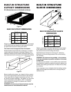
Support tubes
■ Cross ventilation must be incorporated in the
supporting structure. We recommend a minimum of
100 square inches of venting per side.
■ Vents should be on two sides of the structure.
Figures 5 and 6 are references only.
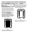
■ Location of the vents should be from the center,
outward.
■ Locate the vents at both the bottom of the structure
and at the top of the structure.
■ The bottom vents should be as close to ground level
as possible. Make sure the vent area is not blocked
by interior supports of the structure.
■ We recommend vents with screens.
■ Access doors to the structure are not considered vents.
■ Clean the vents periodically.
ƽDANGER: Failure to follow recommended minimum
venting instructions can cause gas to collect in the
structure in the event of a gas leak.This may result in
a fire or an explosion which can cause serious bodily
injury or death, and damage to property.
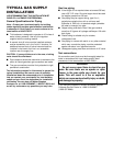
Note: These drawings are only a reference.
VENTILATION
View of left side View of right side
View of front side View of back side
Figure 7
Figure 8