


Special offers from our partners!

Find Replacement BBQ Parts for 20,308 Models. Repair your BBQ today.
Buy Weber Grill Parts. It couldn't be easier. Find your Weber parts here.

WWW.WEbEr.com
®
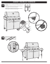
23
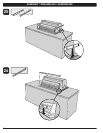
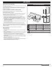
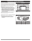
GaS SUPPLY
bUILT-IN GaS LINE LocaTIoNS
3
1
2
c
a
b
1
2
3
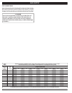
460 660 ToLEraNcES
1 16 1/2" (419.1 mm) 16 1/2" (419.1 mm) ±1/8" (3.2 mm)
2 11 1/8" (282.6 mm) 11 1/8" (282.6 mm) ±1/8" (3.2 mm)
3 2 1/2" (63.5 mm) 2 1/2" (63.5 mm) ±1/8" (3.2 mm)
a Plan view right
b Side view
c Gas inlet
BUILT-IN GAS LINE LOCATIONS
Note: Leave an access in the “island” structure for gas supply and regulator service that
is not inside the grill structure.
Note: Area should be kept clear of sharp, jagged, or extremely abrasive surfaces to
avoid possible damage to gas supply lines. Exercise caution when pulling gas lines
through built-in structure.
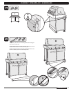
◆
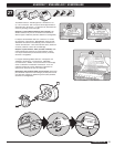
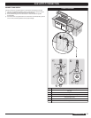
TYPICAL NATURAL GAS SUPPLY INSTALLATION
We recommend that this installation be done by a LICENSED professional.
General Specifications For Piping
Note - Contact your local municipality for building codes regulating outdoor gas grill
installations. In absence of Local Codes, you must conform to the latest edition of
National Fuel Gas Code ANSI Z223.1/NFPA54.
• Thisgrillisdesignedtooperateat4.5inchesofwatercolumnpressure.
• Amanualshut-offvalvemustbeinstalledoutdoors,andbeaccessible,notinthe
“built-in” structure. An additional manual shut-off valve indoors should be installed in
the branch fuel line in an accessible location near the supply line.
m CAUTION: If young children are in the area, a locking valve
should be considered.
• Pipecompoundshouldbeusedwhichisresistanttotheactionofliquidpropanegas
when gas connections are made.
• Thegasconnectionsmustbefirmlyattachedtoarigid,permanentconstruction.
Note: The information provided in this manual is general for typical installations. We
cannot cover all possible installation ideas. We recommend, prior to installation, that you
contact your municipality for local building codes and your local fire department for
installation verification.
If you have any questions, contact Customer Service at 1-800-446-1071.
◆
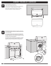
GAS LINE PIPING
• Refertopipingchart.
• Thecorrugatedgaslinefromthemanifoldis58"(1,473.2mm)long.Donotextend
the gas line.
• WehaveprovidedthemeanstomakeanSAE45°flareconnection.Donotusepipe
sealant on this connection.
• Ifthelengthoflinerequireddoesnotexceed50feet,usea5/8"O.D.tube.Onesize
larger should be used for lengths greater than 50 feet. Refer to piping chart.
• Gaspipingmaybecoppertubing,typeKorL;polyethyleneplastictube,witha
minimumwallthicknessof.062"(1.57mm);orstandardweight(schedule40)steelor
wrought iron pipe.
• Coppertubingmustbetin-linedifthegascontainsmorethan0.3gramsofhydrogen
sulfide per 100 cubic feet of gas.
• Plastictubingissuitableonlyforoutdoor,undergrounduse.
• Gaspipingincontactwithearth,oranyothermaterialwhichmaycorrodethepiping,
must be protected against corrosion in an approved manner.
• Undergroundpipingmusthaveaminimumof18"cover.
◆