


Special offers from our partners!

Find Replacement BBQ Parts for 20,308 Models. Repair your BBQ today.
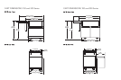
3
2
IMPORTANT: PLEASE READ AND FOLLOW
1. Before beginning, please read these instructions completely and carefully.
2. Do not remove permanently affixed labels, warnings, or plates from product.
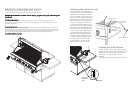
BEFORE INSTALLING GRILL TO CART: Remove drip tray, grill grates, flavor grids, and warming racks
from the grill.
To remove side shelves:
The side shelves on the cart can be removed if needed. This must be done before installing the grill on the cart.
With the shelf in the up position, remove the screws in the shelf support bracket. This will allow you to remove both
the brackets and the shelf.
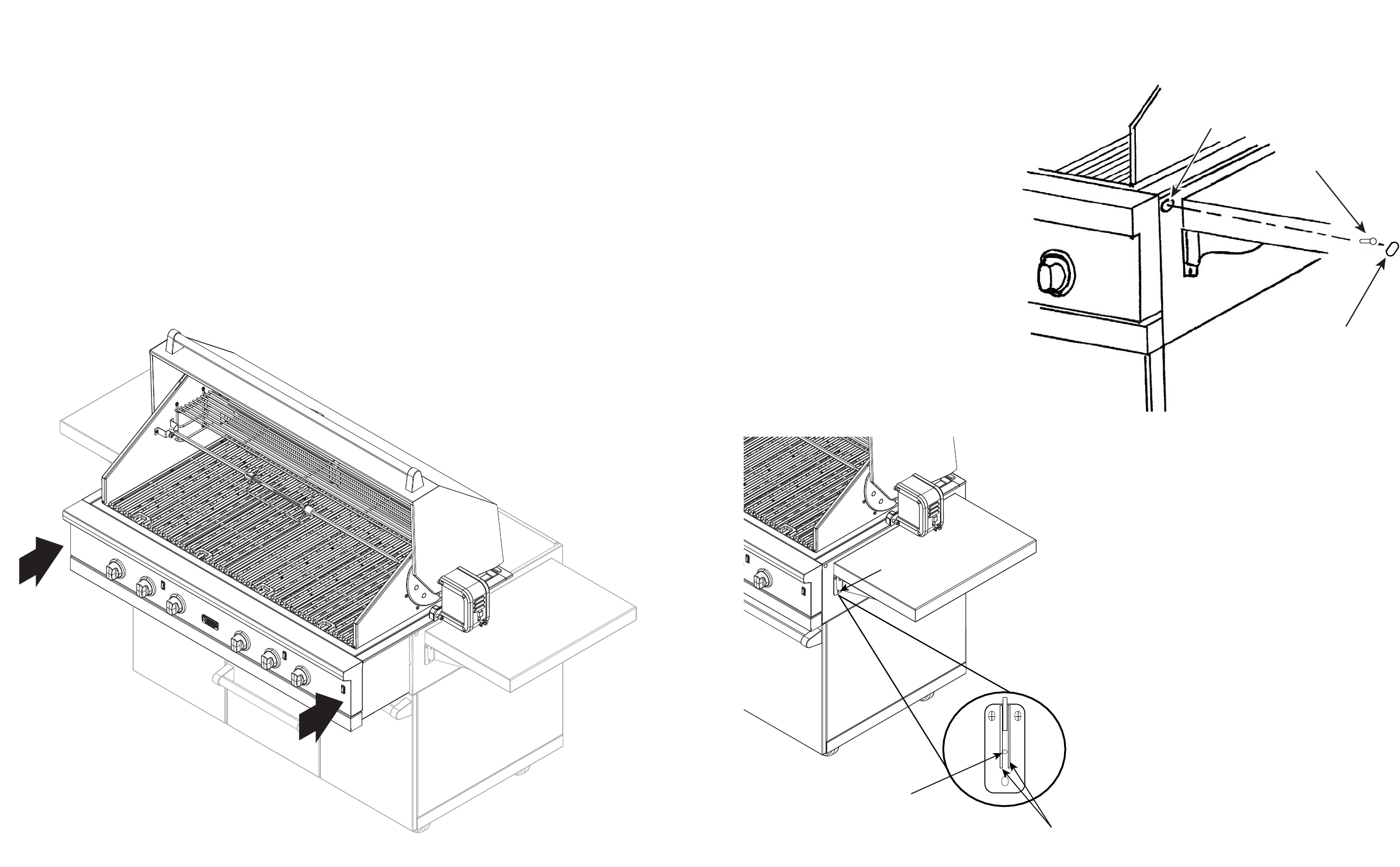
To mount grill to cart:
Always wear gloves when handling the gas grill. Although the grill is deburred prior to shipment, some edges may
still be sharp enough to cause injury during handling. With a minimum of two (2) people, place the grill in the cart with
about 3 to 4 inches hanging out the front making sure that the male fitting on the bottom of the grill is inside the cart.
Push the grill back until the front sides of the cart are flush with the back of the landing ledge on the grill.
Be careful: the grill unit is very heavy!
Attaching the grill to the cart
Once the grill has been mounted on
the cart, the back of the landing ledge
should be flush with the front sides of
the cart. The 5/8” (1.6 cm) hole on the
top front corners of the cart should be
aligned with the receiving holes in the
grill heat shields. If your grill does not
have the receiving holes in the heat
shield, you will need to drill them out
with a 9/64” (.14 cm) drill bit. With the
grill and cart mounted together, place
the drill bit in the 5/8 hole and center
in the 1/4”x3/8” slot. Drill through the
heat shield. Take the #10X3/4” (1.9
cm) sheet metal screws (A) supplied
with the cart and attach the cart sides
to the grill. After securing the grill to
the cart, snap the hole covers (B)
supplied with the cart into the 5/8”
(1.6 cm) holes in the cart corners.
5/8” (1.6 cm) dia. hole
(A) #10 x 3/4” (1.9 cm)
sheet metal screw
(B) 5/8” (1.6 cm) hole cov
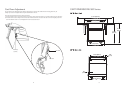
Support
bracket
screws
Shelf
adjustment
screw
Supports
Front View
Leveling the Side Shelves
To level the side shelves, lift the shelf so that the
shelf adjustment screw is visible between the two
supports on the shelf brackets. Turn the screw
with a 3/32” (.2 cm) allen wrench counter
clockwise
to raise the shelf and clockwise to lower the shelf.